AIR CONDITIONING PANEL(for Manual Cooler System) INSPECTION
PROCEDURE
-
INSPECT AIR CONDITIONING CONTROL ASSEMBLY
-

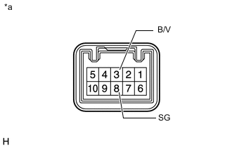
*a Component without harness connected
(Air Conditioning Control Assembly)
Check the blower switch resistance.
-
Measure the resistance according to the value(s) in the table below.
Standard Resistance Tester Connection Condition Specified Condition 9 (LO), 6 (HI), 8 (M1) or 10 (M2) - 5 (E) OFF 10 kΩ or higher 9 (LO) - 5 (E) Blower Switch 1 Below 1 Ω 9 (LO) or 8 (M1) - 5 (E) Blower Switch 1 - 2 Below 1 Ω 9 (LO) or 8 (M1) - 5 (E) Blower Switch 2 Below 1 Ω 9 (LO), 8 (M1) or 10 (M2) - 5 (E) Blower Switch 2 - 3 Below 1 Ω 9 (LO) or 10 (M2) - 5 (E) Blower Switch 3 Below 1 Ω 9 (LO), 6 (HI) or 10 (M2) - 5 (E) Blower Switch 3 - 4 Below 1 Ω 9 (LO) or 6 (HI) - 5 (E) Blower Switch 4 Below 1 Ω If the result is not as specified, replace the air conditioning control assembly.
-
-
*a Component without harness connected
(Air Conditioning Control Assembly)
Check the cooler volume resistance.
-
Measure the resistance according to the value(s) in the table below.
Standard Resistance Tester Connection Switch Position Specified Condition 3 (B/V) - 8 (SG) OFF 10 kΩ or higher 3 (B/V) - 8 (SG) ON to Max Cool 3.6 kΩ to 0 Ω If the result is not as specified, replace the air conditioning control assembly.
-
-