FRONT AIR CONDITIONING UNIT INSTALLATION
CAUTION / NOTICE / HINT
Tech Tips
-
Use the same procedure for RHD and LHD vehicles.
-
The procedure listed below is for LHD vehicles.
-
A bolt without a torque specification is shown in the standard bolt chart.
PROCEDURE
-
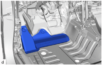
INSTALL NO. 3 AIR DUCT
-
Attach the claw to install the No. 3 air duct.
-
-
INSTALL AIR CONDITIONING UNIT ASSEMBLY
Note
-
Be sure to support the air conditioning unit assembly when installing it because failure to do so may cause the bracket of the air conditioning unit assembly to break.
-
When installing the air conditioning unit assembly, eliminate static electricity by touching the vehicle body to prevent the components from being damaged.
-
Temporarily install the air conditioning unit assembly and instrument panel reinforcement assembly with the nut.
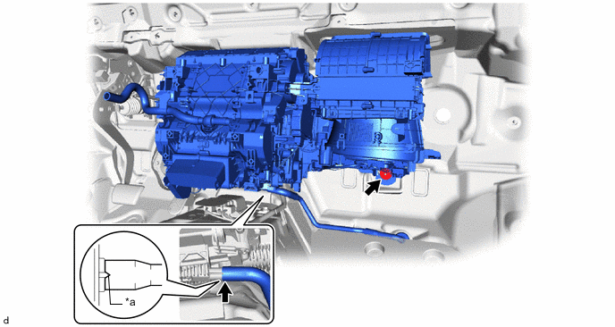
*a Standard Position - - -
Align the standard position, install the drain cooler hose.
-
Tighten the nut.
- Torque:
- 9.8 N*m { 100 kgf*cm, 87 in.*lbf }
-
-
INSTALL DEFROSTER NOZZLE ASSEMBLY
-
Attach the claw to install the defroster nozzle assembly.
-
-
INSTALL INSTRUMENT PANEL REINFORCEMENT ASSEMBLY
Note
-
Be sure to support the air conditioning unit assembly when installing it because failure to do so may cause the bracket of the air conditioning unit assembly to break.
-
When installing the air conditioning unit assembly, eliminate static electricity by touching the vehicle body to prevent the components from being damaged.
-
for Automatic Transmission:
Install the 11 bolts.
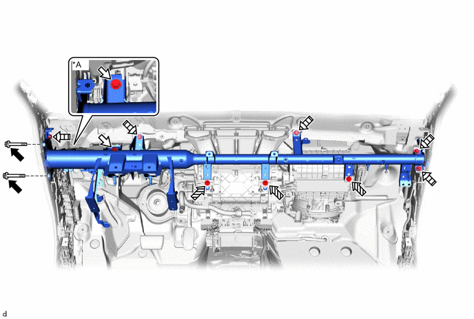
*A for Manual Transmission - - 
Bolt A 
Bolt B 
Bolt C 
Bolt D - Torque:
- Bolt A
- 20 N*m { 204 kgf*cm, 15 ft.*lbf }
- Bolt B
- 18 N*m { 184 kgf*cm, 13 ft.*lbf }
-
for Manual Transmission:
Install the 12 bolts.
- Torque:
- Bolt A
- 20 N*m { 204 kgf*cm, 15 ft.*lbf }
- Bolt B
- 18 N*m { 184 kgf*cm, 13 ft.*lbf }
-
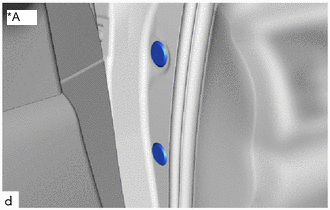
*A for Driver Side Install 2 new hole plugs.
-
-
INSTALL NO. 1 INSTRUMENT PANEL BRACE SUB-ASSEMBLY
-
Nut Bolt Screw Install the No. 1 instrument panel brace sub-assembly with the nut, bolt and 4 screws.
- Torque:
- Bolt, Nut
- 20 N*m { 204 kgf*cm, 15 ft.*lbf }
-
Attach the clamp.
-
-
INSTALL NO. 2 INSTRUMENT PANEL BRACE SUB-ASSEMBLY
-
Nut Bolt Screw Install the No. 2 instrument panel brace sub-assembly with the nut, bolt and 3 screws.
- Torque:
- Bolt, Nut
- 20 N*m { 204 kgf*cm, 15 ft.*lbf }
-
-
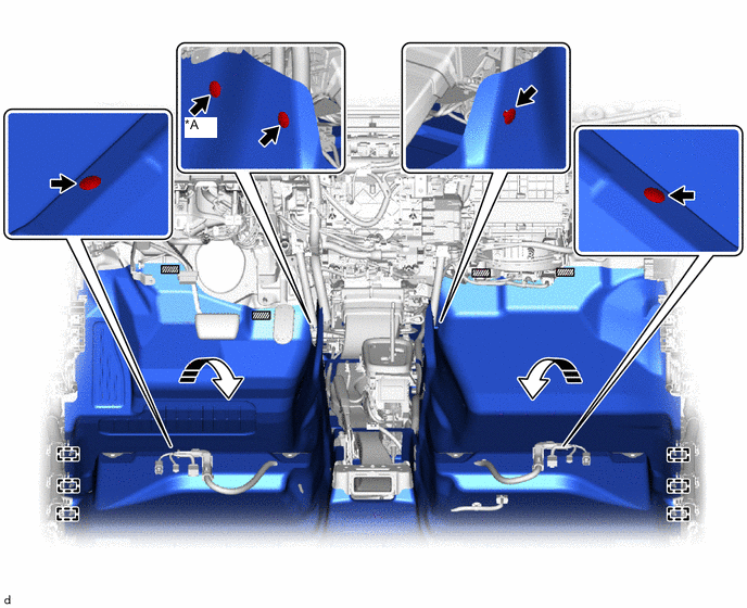
TIGHTEN AIR CONDITIONING UNIT ASSEMBLY
-
Tighten the 2 screws and 3 bolts in the order shown in the illustration.
- Torque:
- Bolt
- 9.8 N*m { 100 kgf*cm, 87 in.*lbf }
Bolt Screw
-
-
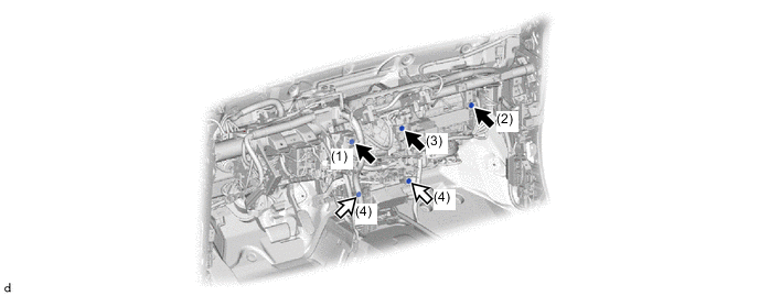
CONNECT INSTRUMENT PANEL WIRE
-
Install each bolt, nut and screw, and then connect the instrument panel wire.
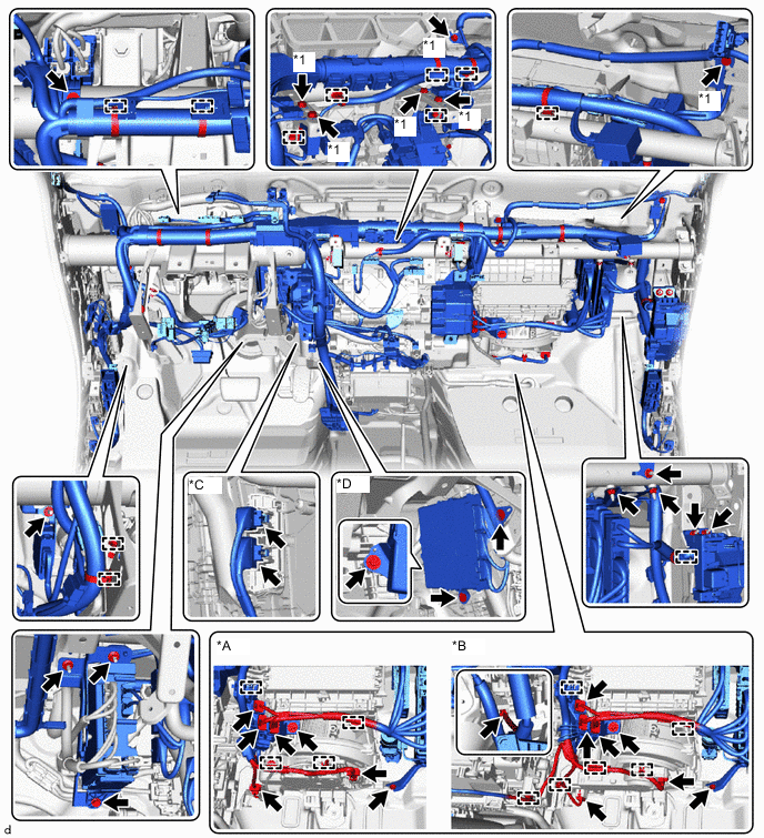
*A for Automatic Air Conditioning System *B for Manual Air Conditioning System, Manual Cooler System *C w/ PTC Heater *D w/ Stop and Start System *1 Ground Wire - - -
Connect each connector and attach each clamp.
-
Install each bolt and each ground wire.
- Torque:
- 8.3 N*m { 85 kgf*cm, 73 in.*lbf }
-
for Automatic Air Conditioning System:
-
Attach the clamp.
-
Connect the connector.
-
-
for Manual Air Conditioning System, Manual Cooler System:
-
Attach the clamp.
-
Connect the connector.
-
-
-
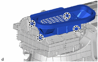
INSTALL NO. 1 REAR AIR DUCT (w/ Rear Foot Duct)
-
Attach the claw to install the No. 1 rear air duct.
-
-
INSTALL NO. 3 REAR AIR DUCT (w/ Rear Foot Duct)
-
Attach the claw to install the No. 3 rear air duct.
-
-
INSTALL NO. 2 REAR AIR DUCT (w/ Rear Foot Duct)
-
Attach the claw to install the No. 2 rear air duct.
-
-
INSTALL NO. 5 REAR AIR DUCT (w/ Rear Foot Duct)
-
Attach the claw to install the No. 5 rear air duct.
-
-
INSTALL NO. 4 REAR AIR DUCT (w/ Rear Foot Duct)
-
Attach the claw to install the No. 4 rear air duct.
-
-
INSTALL NO. 1 CONSOLE BOX DUCT (w/ Rear Resistor Duct)
-
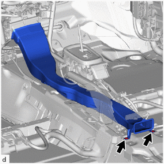
for Automatic Transmission:
-
Install the No. 1 console box duct with the 2 clips.
-
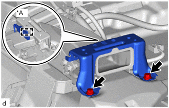
*A w/ Entry and Start System w/ Entry and Start System:
Attach the clamp to install the No. 2 console box mounting bracket.
-
Install the 2 bolts.
-
-

for Manual Transmission:
-
Install the No. 1 console box duct with the 3 clips.
-
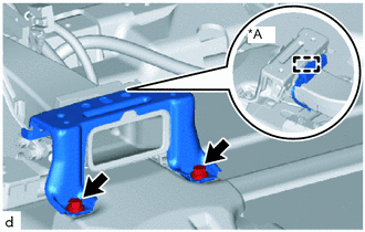
*A w/ Entry and Start System w/ Entry and Start System:
Attach the clamp to install the No. 2 console box mounting bracket.
-
Install the 2 bolts.
-
-
-
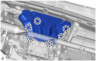
INSTALL NO. 3 DASH PANEL INSULATOR PAD
-
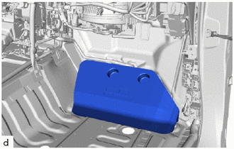
Install the No. 3 dash panel insulator pad.
-
-
INSTALL NO. 2 DASH PANEL INSULATOR PAD
-
Install the No. 2 dash panel insulator pad.
-
-
INSTALL NO. 1 INSTRUMENT PANEL INNER BRACKET COVER LH (for LHD)
-
Install the No. 1 instrument panel inner bracket cover LH with the 3 clips.
-
-
INSTALL FRONT FLOOR CARPET ASSEMBLY
-
Attach the guide to install the front floor carpet assembly to the original position as shown in the illustration.
*A for LHD - - 
Fastener 
Install in this Direction -
Attach each fastener.
-
for LHD:
Install the 5 clips.
-
for RHD:
Install the 4 clips.
-
-
INSTALL LOWER CENTER PILLAR GARNISH LH (for Double Cab)
-
INSTALL LOWER CENTER PILLAR GARNISH RH (for Double Cab)
-
INSTALL REAR DOOR SCUFF PLATE LH (for Double Cab)
-
INSTALL REAR DOOR SCUFF PLATE RH (for Double Cab)
-
INSTALL COWL SIDE TRIM BOARD LH
-
INSTALL FRONT DOOR SCUFF PLATE LH
-
for Double Cab:
-
for Single Cab:
-
for Smart Cab:
-
-
INSTALL COWL SIDE TRIM BOARD RH
-
INSTALL FRONT DOOR SCUFF PLATE RH
-
for Double Cab:
-
for Single Cab:
-
for Smart Cab:
-
-
INSTALL STEERING COLUMN ASSEMBLY
-
INSTALL NO. 1 AIR DUCT
-
Attach the claw to install the No. 1 air duct.
Note
If the No. 1 air duct is reused, it may fall off or abnormal noise may occur. Therefore, make sure to replace it with a new one.
-
Install the bolt.
- Torque:
- 9.8 N*m { 100 kgf*cm, 87 in.*lbf }
-
-
INSTALL NO. 2 AIR DUCT
-
Attach the claw to install the No. 2 air duct.
Note
If the No. 2 air duct is reused, it may fall off or abnormal noise may occur. Therefore, make sure to replace it with a new one.
-
-
INSTALL TELEPHONE TRANSCEIVER ASSEMBLY (w/ Telematics Transceiver)
-
INSTALL LOWER INSTRUMENT PANEL SUB-ASSEMBLY
-
INSTALL CONSOLE BOX ASSEMBLY (w/ Console Box Lid)
-
INSTALL FRONT CONSOLE BOX (w/o Console Box Lid)
-
INSTALL FRONT SEAT ASSEMBLY LH
-
for Manual Seat:
-
for Power Seat:
-
for Bench Seat Type:
-
-
INSTALL FRONT SEAT ASSEMBLY RH
Tech Tips
Use the same procedure described for the LH side.
-
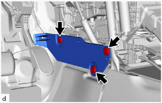
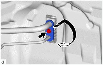
INSTALL HEATER GROMMET (w/ Heater)
-
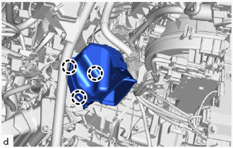
Press the marked parts to attach the claw and install the heater grommet.
Note
-
Securely install the heater grommet in order to prevent water ingress.
-
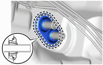
Install the heater grommet so that there is no clearance between the grommet and heater pipe.
-
-
-
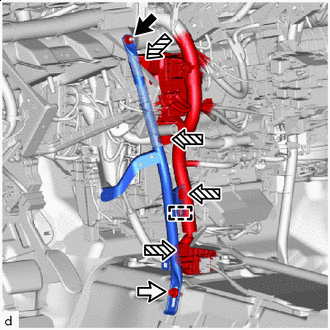
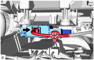
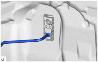
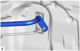
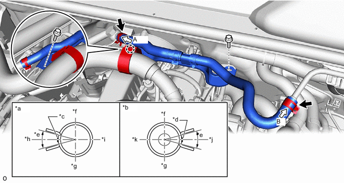
CONNECT HEATER WATER INLET HOSE (w/ Heater)
-
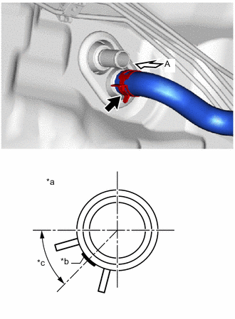
*a View A *b for 1GR-FE: Marking (Yellow)
for 1GD-FTV, 2GD-FTV: Marking (Yellow)
for 2KD-FTV: Marking (Yellow)
for 1TR-FE, 2TR-FE: Marking (Yellow)
for 5L-E: Marking (Yellow)
*c Clip Installation Angle (45°) Connect the heater water inlet hose with the marking facing left and attach the clip within the area shown in the illustration.
Note
Do not apply excessive force to the heater water inlet hose.
-
-
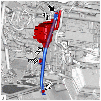
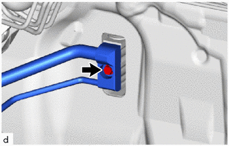
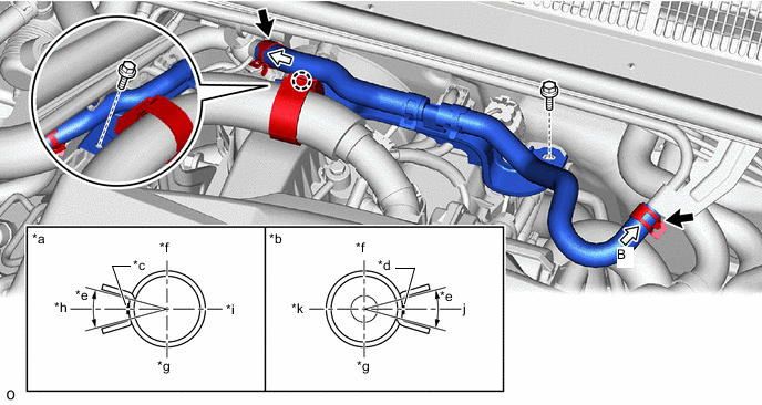
CONNECT HEATER WATER OUTLET HOSE (w/ Heater)
-
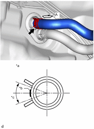
*a View A *b for 1GR-FE: Marking (White)
for 1GD-FTV, 2GD-FTV: Marking (White)
for 2KD-FTV: Marking (White)
for 1TR-FE, 2TR-FE: Marking (White)
for 5L-E: Marking (White)
*c Clip Installation Angle (40°) Connect the heater water outlet hose with the marking facing left and attach the clip within the area shown in the illustration.
Note
Do not apply excessive force to the heater water outlet hose.
-
-
INSTALL INTAKE AIR SURGE TANK (for 1GR-FE)
-
CONNECT AIR CONDITIONER TUBE AND ACCESSORY ASSEMBLY (except 1GD-FTV, 2GD-FTV)
-
Remove the vinyl tape from the air conditioner tube and accessory assembly.
-
Sufficiently apply compressor oil to a new O-ring and the fitting surface of the air conditioner tube and accessory assembly.
Compressor Oil ND-OIL 8 or equivalent -
Install the O-ring to the air conditioner tube and accessory assembly.
Note
Keep the O-ring and O-ring fitting surfaces free of foreign matter.
-
Connect the air conditioner tube and accessory assembly.
-
-
CONNECT SUCTION PIPE SUB-ASSEMBLY (except 1GD-FTV, 2GD-FTV)
-
Remove the vinyl tape from the suction pipe sub-assembly.
-
Sufficiently apply compressor oil to a new O-ring and the fitting surface of the suction pipe sub-assembly.
Compressor Oil ND-OIL 8 or equivalent -
Install the O-ring to the suction pipe sub-assembly.
Note
Keep the O-ring and O-ring fitting surfaces free of foreign matter.
-
Connect the suction pipe sub-assembly.
-
Install in this Direction Rotate the hook connector as shown in the illustration.
-
Insert the pipe joint into the fitting hole securely and tighten the bolt.
- Torque:
- 5.4 N*m { 55 kgf*cm, 48 in.*lbf }
-
-
CONNECT AIR CONDITIONER TUBE AND ACCESSORY ASSEMBLY (for 1GD-FTV, 2GD-FTV)
-
Remove the vinyl tape from the air conditioner tube and accessory assembly.
-
Sufficiently apply compressor oil to 2 new O-rings and the fitting surface of the air conditioner tube and accessory assembly.
Compressor Oil ND-OIL 8 or equivalent -
Install the 2 O-rings to the air conditioner tube and accessory assembly.
Note
Keep the O-rings and O-ring fitting surfaces free of foreign matter.
-
Connect the air conditioner tube and accessory assembly.
-
Tighten the bolt.
- Torque:
- 5.4 N*m { 55 kgf*cm, 48 in.*lbf }
-
-
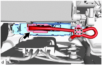
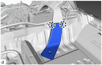
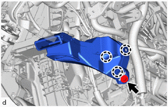
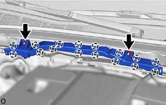
INSTALL VACUUM HOSE ASSEMBLY (for GD Series Engine, LHD)
-
Install the vacuum hose assembly with the 2 bolts.
- Torque:
- 10 N*m { 102 kgf*cm, 7 ft.*lbf }
-
Attach the claw.
-
Connect the vacuum hose with the marking facing left and attach the clip within the area shown in the illustration.
Note
Do not apply excessive force to the vacuum hose.
*a View A *b View B *c Marking (White) *d Marking (Pink) *e Clip Installation Angle (30°) *f Upper *g Lower *h Front *i Rear j Left *k Right - -
-
-
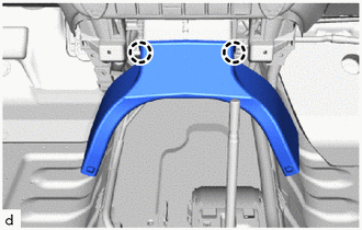
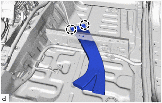
INSTALL NO. 2 WIRING HARNESS PROTECTOR (for GD Series Engine, LHD)
-
Attach the claw to install the No. 2 wiring harness protector.
-
Install the 2 nuts.
- Torque:
- 8.4 N*m { 86 kgf*cm, 74 in.*lbf }
-
-
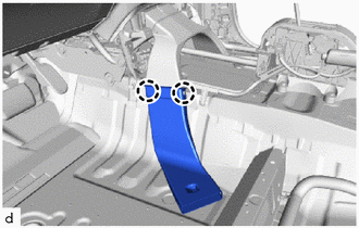
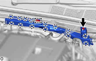
INSTALL VACUUM HOSE ASSEMBLY (for GD Series Engine, RHD)
-
Install the vacuum hose assembly with the 2 bolts.
- Torque:
- 10 N*m { 102 kgf*cm, 7 ft.*lbf }
-
Attach the claw.
-
Connect the vacuum hose with the marking facing left and attach the clip within the area shown in the illustration.
Note
Do not apply excessive force to the vacuum hose.
*a View A *b View B *c Marking (White) *d Marking (Pink) *e Clip Installation Angle (30°) *f Upper *g Lower *h Front *i Rear j Left *k Right - -
-
-
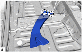
INSTALL NO. 2 WIRING HARNESS PROTECTOR (for GD Series Engine, RHD)
-
Attach the claw and guide to install the No. 2 wiring harness protector.
-
Install the nut.
- Torque:
- 8.4 N*m { 86 kgf*cm, 74 in.*lbf }
-
-
ADD ENGINE COOLANT (w/ Heater)
-
for 1GR-FE:
-
for 1GD-FTV:
-
for 2GD-FTV:
-
for 2KD-FTV:
-
for 1TR-FE:
-
for 2TR-FE:
-
for 5L-E:
-
-
INSPECT FOR COOLANT LEAK (w/ Heater)
-
for 1GR-FE:
-
for 1GD-FTV:
-
for 2GD-FTV:
-
for 2KD-FTV:
-
for 1TR-FE:
-
for 2TR-FE:
-
for 5L-E:
-
-
CHARGE AIR CONDITIONING SYSTEM WITH REFRIGERANT
-
WARM UP ENGINE
-
INSPECT FOR REFRIGERANT LEAK
-
INITIALIZATION SERVO MOTOR (for Automatic Air Conditioning System)