CAUTION / NOTICE / HINT
-
Use the same procedure for RHD and LHD vehicles.
-
The procedure listed below is for LHD vehicles.
w/ Airbag System:
Some of these service operations affect the SRS airbag system. Read the precautionary notices concerning the SRS airbag system before servicing.
for Type A:Click here
for Type B:Click here
PROCEDURE
- Click here
RECOVER REFRIGERANT FROM REFRIGERATION SYSTEM
- Click here
DRAIN ENGINE COOLANT (w/ Heater)
-
for 1GR-FE:
-
for 1GD-FTV:
-
for 2GD-FTV:
-
for 1KD-FTV:
-
for 2KD-FTV:
-
for 1TR-FE:
-
for 2TR-FE:
-
- Click here
REMOVE NO. 2 WIRING HARNESS PROTECTOR (for GD Series Engine, LHD)
-
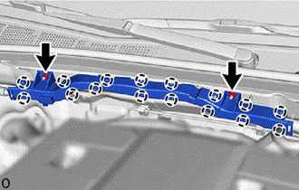
Remove the 2 nuts.
-
Detach the claw and remove the No. 2 wiring harness protector.
-
- Click here
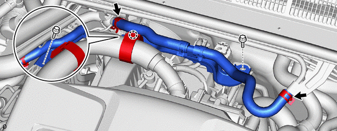
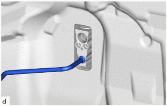
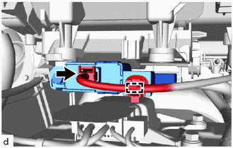
REMOVE VACUUM HOSE ASSEMBLY (for GD Series Engine, LHD)
-
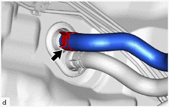
Using pliers, grip the claws of the clip and slide the clip to disconnect the vacuum hose.
Note:Do not apply excessive force to the vacuum hose.
-
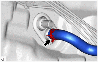
Detach the claw.
-
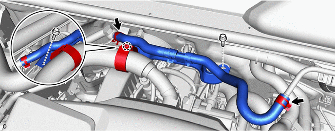
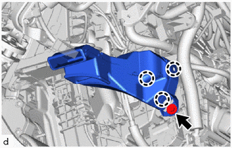
Remove the 2 bolts and remove the vacuum hose assembly.
-
- Click here
REMOVE NO. 2 WIRING HARNESS PROTECTOR (for GD Series Engine, RHD)
-
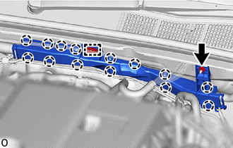
Remove the 2 nuts.
-
Detach the claw, guide and remove the No. 2 wiring harness protector.
-
- Click here
REMOVE VACUUM HOSE ASSEMBLY (for GD Series Engine, RHD)
-
Using pliers, grip the claws of the clip and slide the clip to disconnect the vacuum hose.
Note:Do not apply excessive force to the vacuum hose.
-
Detach the claw.
-
Remove the 2 bolts and remove the vacuum hose assembly.
-
- Click here
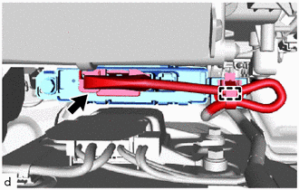
DISCONNECT AIR CONDITIONER TUBE AND ACCESSORY ASSEMBLY (for 1GD-FTV, 2GD-FTV)
-
Remove the bolt and disconnect the air conditioner tube and accessory assembly.
-
Remove the 2 O-rings from the air conditioner tube and accessory assembly.
Note:Seal the openings of the disconnected parts using vinyl tape to prevent the entry of moisture and foreign matter.
-
- Click here
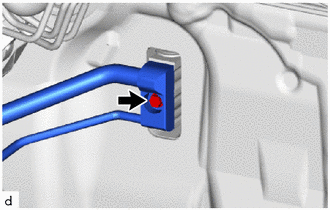
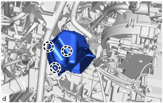
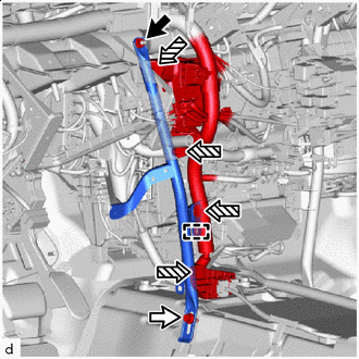
DISCONNECT SUCTION PIPE SUB-ASSEMBLY (except 1GD-FTV, 2GD-FTV)
-
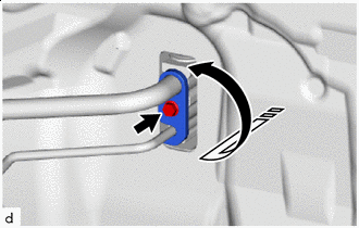

Remove in this Direction Remove the bolt and rotate the hook connector as shown in the illustration.
-
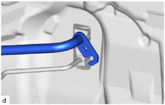
Disconnect the suction pipe sub-assembly.
-
Remove the O-ring from the suction pipe sub-assembly.
Note:Seal the openings of the disconnected parts using vinyl tape to prevent the entry of moisture and foreign matter.
-
- Click here
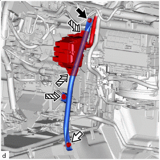
DISCONNECT AIR CONDITIONER TUBE AND ACCESSORY ASSEMBLY (except 1GD-FTV, 2GD-FTV)
-
Disconnect the air conditioner tube and accessory assembly.
-
Remove the O-ring from the air conditioner tube and accessory assembly.
Note:Seal the openings of the disconnected parts using vinyl tape to prevent the entry of moisture and foreign matter.
-
- Click here
REMOVE INTAKE AIR SURGE TANK (for 1GR-FE)
- Click here
DISCONNECT HEATER WATER OUTLET HOSE (w/ Heater)
-
Using pliers, grip the claws of the clip and slide the clip to disconnect the heater water outlet hose.
Note:
-
Do not apply excessive force to the water hose and heater water outlet hose.
-
Prepare a drain pan or cloth in case the coolant leaks.
-
-
- Click here
DISCONNECT HEATER WATER INLET HOSE (w/ Heater)
-
Using pliers, grip the claws of the clip and slide the clip to disconnect the heater water inlet hose.
Note:
-
Do not apply excessive force to the water hose and heater water inlet hose.
-
Prepare a drain pan or cloth in case the coolant leaks.
-
-
-
Click here
REMOVE HEATER GROMMET (w/ Heater)
-
Detach the claw and remove the heater grommet.
-
- Click here
REMOVE FRONT SEAT ASSEMBLY LH
-
for Manual Seat:
-
for Power Seat:
-
for Bench Seat Type:
-
- Click here
REMOVE FRONT SEAT ASSEMBLY RH
Tip:Use the same procedure described for the LH side.
- Click here
REMOVE LOWER INSTRUMENT PANEL SUB-ASSEMBLY
- Click here
REMOVE CONSOLE BOX ASSEMBLY (w/ Console Box Lid)
- Click here
REMOVE FRONT CONSOLE BOX (w/o Console Box Lid)
- Click here
REMOVE NO. 1 AIR DUCT
-
Remove the bolt.
-
Detach the claw and remove the No. 1 air duct.
Note:
-
When removing, do not crack or deform the lower heater case of the air conditioning radiator assembly.
-
If the No. 1 air duct is reused, it may fall off or abnormal noise may occur. Therefore, make sure to replace it with a new one.
-
-
- Click here
REMOVE NO. 2 AIR DUCT
-
Detach the claw and remove the No. 2 air duct.
Note:
-
When removing, do not crack or deform the lower heater case of the air conditioning radiator assembly.
-
If the No. 2 air duct is reused, it may fall off or abnormal noise may occur. Therefore, make sure to replace it with a new one.
-
-
- Click here
REMOVE STEERING COLUMN ASSEMBLY
- Click here
REMOVE FRONT DOOR SCUFF PLATE LH
-
for Double Cab:
-
for Single Cab:
-
for Smart Cab:
-
- Click here
REMOVE COWL SIDE TRIM BOARD LH
- Click here
REMOVE FRONT DOOR SCUFF PLATE RH
-
for Double Cab:
-
for Single Cab:
-
for Smart Cab:
-
- Click here
REMOVE COWL SIDE TRIM BOARD RH
- Click here
REMOVE REAR DOOR SCUFF PLATE LH (for Double Cab)
- Click here
REMOVE REAR DOOR SCUFF PLATE RH (for Double Cab)
- Click here
REMOVE LOWER CENTER PILLAR GARNISH LH (for Double Cab)
- Click here
REMOVE LOWER CENTER PILLAR GARNISH RH (for Double Cab)
- Click here
REMOVE FRONT FLOOR CARPET ASSEMBLY
-
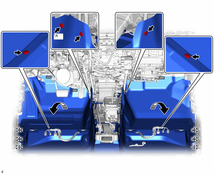
*A for LHD - - 
Fastener Remove in this Direction for LHD:
Remove the 5 clips.
-
for RHD:
Remove the 4 clips.
-
Detach each fastener.
-
Detach the guide and fold back the front floor carpet assembly as shown in the illustration.
-
-
Click here
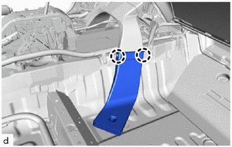
REMOVE NO. 1 INSTRUMENT PANEL INNER BRACKET COVER LH (for LHD)
-
Remove the 3 clips and No. 1 instrument panel inner bracket cover LH
-
- Click here
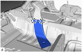
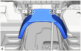
REMOVE NO. 3 DASH PANEL INSULATOR PAD
-
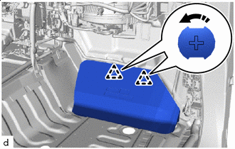
Remove in this Direction Remove the No. 3 dash panel insulator pad as shown in the illustration.
-
- Click here
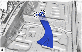
REMOVE NO. 2 DASH PANEL INSULATOR PAD
-
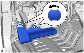
Remove in this Direction Remove the No. 2 dash panel insulator pad as shown in the illustration.
-
- Click here
REMOVE NO. 1 CONSOLE BOX DUCT (w/ Rear Resistor Duct)
-
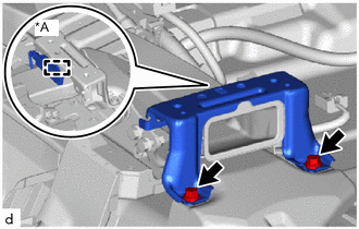
*A w/ Smart Entry and Start System for Automatic Transmission:
-
Remove the 2 bolts.
-
w/ Smart Entry and Start System:
Detach the clamp and remove the No. 2 console box mounting bracket.
-
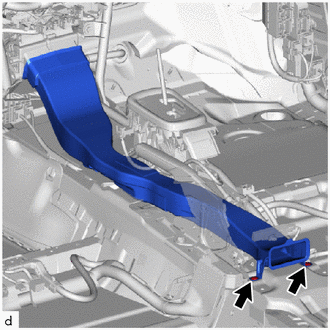
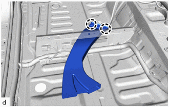
Remove the 2 clips and No. 1 console box duct.
-
-
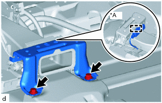
*A w/ Smart Entry and Start System for Manual Transmission:
-
Remove the 2 bolts.
-
w/ Smart Entry and Start System:
Detach the clamp and remove the No. 2 console box mounting bracket.
-

Remove the 3 clips and No. 1 console box duct.
-
-
- Click here
REMOVE NO. 4 REAR AIR DUCT (w/ Rear Foot Duct)
-
Detach the claw and remove the No. 4 rear air duct.
-
- Click here
REMOVE NO. 5 REAR AIR DUCT (w/ Rear Foot Duct)
-
Detach the claw and remove the No. 5 rear air duct.
-
- Click here
REMOVE NO. 2 REAR AIR DUCT (w/ Rear Foot Duct)
-
Detach the claw and remove the No. 2 rear air duct.
-
- Click here
REMOVE NO. 3 REAR AIR DUCT (w/ Rear Foot Duct)
-
Detach the claw and remove the No. 3 rear air duct.
-
- Click here
REMOVE NO. 1 REAR AIR DUCT (w/ Rear Foot Duct)
-
Remove the 2 clips and remove the No. 1 rear air duct.
-
- Click here
REMOVE NO. 1 INSTRUMENT PANEL BRACE SUB-ASSEMBLY
-

Nut 
Bolt 
Screw Detach the clamp.
-
Remove the nut, bolt, 4 screws and No. 1 instrument panel brace sub-assembly.
-
- Click here
REMOVE NO. 2 INSTRUMENT PANEL BRACE SUB-ASSEMBLY
-
Nut Bolt Screw Remove the nut, bolt, 3 screws and No. 2 instrument panel brace sub-assembly.
-
- Click here
DISCONNECT INSTRUMENT PANEL WIRE
-
for Automatic Air Conditioning System:
-
Disconnect the connector.
-
Detach the clamp.
-
-
for Manual Air Conditioning System, Manual Cooler System:
-
Disconnect the connector.
-
Detach the clamp.
-
-
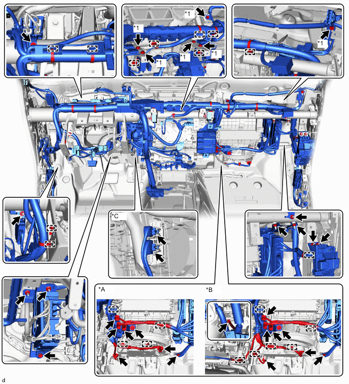
*A for Manual Air Conditioning System, Manual Cooler System *B for Automatic Air Conditioning System *C w/ PTC Heater - - *1 Ground Wire - - Remove each bolt and each ground wire.
-
Disconnect each connector and detach each clamp.
-
Remove each bolt, nut and screw, and then disconnect the instrument panel wire.
-
- Click here
REMOVE INSTRUMENT PANEL REINFORCEMENT ASSEMBLY
Note:
-
Be sure to support the air conditioning unit assembly when removing it because failure to do so may cause the bracket of the air conditioning unit assembly to break.
-
When removing the air conditioning unit assembly, eliminate static electricity by touching the vehicle body to prevent the components from being damaged.
-
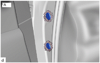
*A for Driver Side Protective Tape Put protective tape around the hole plug.
-
Using a screwdriver with its tip wrapped with protective tape, remove the 2 hole plugs.
-
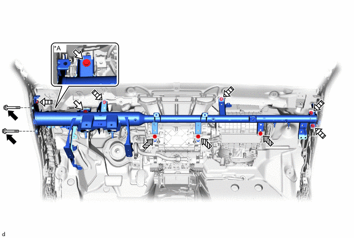
*A for Manual Transmission - - Bolt A Bolt B Bolt C 
Bolt D for Automatic Transmission:
Remove the 11 bolts.
-
for Manual Transmission:
Remove the 12 bolts.
-
-
Click here
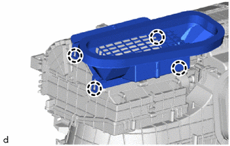
REMOVE DEFROSTER NOZZLE ASSEMBLY
-
Detach the claw and remove the defroster nozzle assembly.
-
- Click here
REMOVE AIR CONDITIONING UNIT ASSEMBLY
Note:
-
Be sure to support the air conditioning unit assembly when removing it because failure to do so may cause the bracket of the air conditioning unit assembly to break.
-
When disassembling the air conditioning unit assembly, eliminate static electricity by touching the vehicle body to prevent the components from being damaged.
-
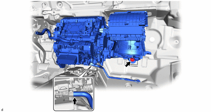
Disconnect the drain cooler hose.
-
Remove the nut and air conditioning unit assembly and instrument panel reinforcement assembly.
-
- Click here
REMOVE NO. 3 AIR DUCT
-
Detach the claw and remove the No. 3 air duct.
-