AIR CONDITIONING SYSTEM(for Automatic Air Conditioning System) SYSTEM DESCRIPTION
-
GENERAL
-
The air conditioning system has the following controls.
Control Outline Neural Network Control This control is capable of performing complex control by artificially simulating the information processing method of the nervous system of living organisms in order to establish a complex input/output relationship similar to that of a human brain. Outlet Air Temperature Control Based on the temperature set by the temperature control dial, neural network control calculates outlet air temperature based on input signals from various sensors. Blower Control Controls the blower motor in accordance with the airflow volume that has been calculated by neural network control based on the input signals from various sensors. Air Outlet Control Automatically switches the air outlets in accordance with the outlet mode that has been calculated by neural network control. In accordance with the engine coolant temperature, ambient air temperature, amount of sunlight, required airflow volume, outlet temperature and vehicle speed, this control automatically switches the blower outlet to foot and defroster mode to prevent the windows from becoming fogged up when the ambient air temperature is low. Air Inlet Control Automatically controls the air inlet control damper to help achieve the calculated outlet air temperature that is required. Drives the air inlet control servo motor according to the operation of the air inlet control switch and moves the dampers to the fresh or recirculation position. Compressor Control The air conditioning amplifier assembly calculates the target evaporator temperature (which is calculated by the room temperature sensor, ambient temperature sensor, and solar sensor) and the actual evaporator temperature that is detected by the evaporator temperature sensor in order to control the compressor. Turns the air conditioning from off to on automatically while the AUTO button is on. Defroster Control Defroster control logic is used to improve defroster performance. ECO Mode Control When the ECO mode cancel switch is turned off, the air conditioning amplifier assembly limits the air conditioning system performance. Diagnosis A Diagnostic Trouble Code (DTC) is stored in memory when the air conditioning amplifier detects a problem with the air conditioning system.
-
-
MODE POSITION AND DAMPER OPERATION
-
Mode Position and Damper Operation
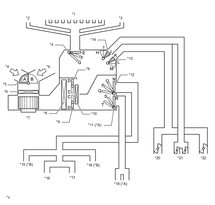
*A w/ Rear Face Register *B w/ Rear Footwell Register *1 Front Defroster *2 Side Defroster (LH) *3 Side Defroster (RH) *4 No. 1 Air Conditioning Radiator Damper Servo Sub-assembly
-
- Front Mode (for Defroster)
*5 No. 1 Blower Damper Servo Sub-assembly
-
- Fresh/Recirculation
*6 Clean Air Filter (Air Refiner Element) *7 Blower with Fan Motor Sub-assembly *8 No. 1 Cooler Evaporator *9 No. 1 Air Conditioning Radiator Damper Servo Sub-assembly
-
- Front Side Air Mix
*10 Heater Radiator Unit Sub-assembly *11 No. 2 Air Conditioning Radiator Damper Servo Sub-assembly
-
- Rear Mode
*12 No. 1 Air Conditioning Radiator Damper Servo Sub-assembly
-
- Front Mode (for Footwell Duct)
*13 No. 1 Air Conditioning Radiator Damper Servo Sub-assembly
-
- Front Mode (for Side Register)
*14 No. 1 Air Conditioning Radiator Damper Servo Sub-assembly
-
- Front Mode (for Center Register)
*15 Rear Footwell Duct (LH) *16 Footwell Duct (RH) *17 Footwell Duct (RH) *18 Rear Footwell Duct (RH) *19 Rear Face Register Duct *20 Side Register (LH) *21 Center Register *22 Side Register (RH) *a Recirculated Air *b Fresh Air *c This illustration shows the dampers and air outlets schematically. Actual shapes and numbers of parts will differ from those shown in the illustration. - - Mode Position and Damper Operation Chart Damper Operation Position Damper Position Operation Air Inlet Control Damper FRESH A Brings in fresh air. RECIRCULATION B Recirculates internal air. Air Mix Control Damper HI - LO C - D Varies the mixture ratio of the cool air and the hot air in order to regulate the temperature continuously from HI to LO. Mode Control Damper FACE E, H, M, N, T Blows air out of the center register, side register and rear face register*1. BI-LEVEL E, I, L, P, S Blows air out of the center register, side register, footwell register, rear face register*1 and rear footwell register*2. FOOT F, J, K, Q, R Blows air out of the footwell register duct and rear footwell register*2. A small amount of air also blows out from the side register, front defroster and side defroster. FOOT/DEF F, J, K, P, R Defrosts the windshield through the front defroster and side defroster. At the same time, air is blown out from the footwell register and rear footwell register*2. A small amount of air also blows out from the side register. DEF G, J, K, N, R Defrosts the windshield through the front defroster and side defroster. A small amount of air also blows out from the side register.
-
*1: w/ Rear Face Register
-
*2: w/ Rear Footwell Register
-
-
-
AIR OUTLETS AND AIRFLOW VOLUME
-
Air Outlets and Airflow Volume
Indication Mode Center Register Side Register Footwell Register and Rear Footwell Register*2 Front Defroster, Side Defroster Rear Face Register*1 A B C, F D E 
FACE 
- - 
BI-LEVEL 
- 

FOOT - - 
FOOT/DEF - - 
DEF - - -
-
*1: w/ Rear Face Register
-
*2: w/ Rear Footwell Register
Tech Tips
The circle size (○) is proportional to the amount of air flow.
-
-
-
INITIALIZATION CONTROL
-
Initialization:
-
The air conditioning amplifier assembly sends control commands to the servo motors. In order to move the servo motors correctly, the base position (initialization point) must be detected.
Tech Tips
During initialization (while the AUTO indicator is illuminated), no operations can be received.
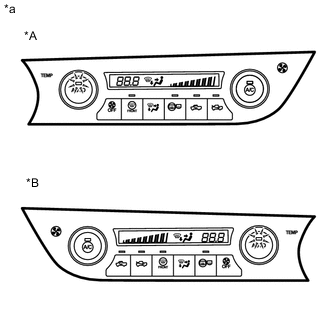
*A for LHD *B for RHD *a Example
-
-
Symptoms during initialization failure:
Cause Malfunction Suspected Area DTC DTC Detection Condition Servo motor operation defective, position deviated Foreign object caught in servo motor, damper gear stuck, etc.
-
Air conditioning unit assembly
-
No. 1 air conditioning radiator servo motor sub-assembly
-
No. 2 air conditioning radiator servo motor sub-assembly
-
Gear, ring
-
DTC B1441/41
-
DTC B1442/42
-
DTC B1443/43
-
DTC B1449/49
The air conditioning amplifier assembly is unable to move the servo motors. As a result, the servo motor position detection pulse output remains constant, and a servo motor operation defective DTC is output after 30 seconds elapse. Servo motor locked Single servo motor malfunctioning, stuck, etc.
-
No. 1 air conditioning radiator servo motor sub-assembly
-
No. 2 air conditioning radiator servo motor sub-assembly
-
DTC B1441/41
-
DTC B1442/42
-
DTC B1443/43
-
DTC B1449/49
The air conditioning amplifier assembly is unable to move the servo motors. As a result, the servo motor position detection pulse output remains constant, and a servo motor operation defective DTC is output after 30 seconds elapse. BUS communication malfunction Connector not connected properly, wire harness pinched Harness or connector DTC B1497 The air conditioning amplifier assembly outputs this DTC 10 seconds after a BUS communication malfunction occurs. Battery voltage drop (including open circuits) Battery voltage drop when ignition switch to ON (including remote start) Air conditioning amplifier assembly (battery voltage) - - No air conditioning amplifier assembly position information Malfunction in CPU or air conditioning amplifier assembly internal memory which saves servo motor position data Air conditioning amplifier assembly (battery voltage) - - -
-
-
COMPRESSOR CONTROL
Item Outline Note Refrigerant pressure abnormality judgment The air conditioning amplifier assembly detects the refrigerant pressure and keeps the cooler compressor off while a refrigerant pressure abnormality is input.
-
Judgment pressure: 0.1762 MPa or lower, or 3.0254 MPa or higher
The refrigerant pressure is also determined to be abnormal when the ambient temperature is low. Frost prevention The air conditioning amplifier assembly receives the refrigerant pressure and temperature detected by the No. 1 cooler thermistor (post-evaporator sensor) and calculates capacity output control for the compressor in order to perform frost control. When the air conditioning amplifier assembly determines that frost may form, it prevents evaporator frost by outputting a lower compressor operation variable or turning the compressor off. - Acceleration cut When accelerating, the air conditioning amplifier assembly lowers the operating capacity of the compressor based on air conditioning cut signals from the ECM in order to ensure acceleration performance. - Low-speed cut When at low engine speeds, the air conditioning amplifier assembly turns the compressor off based on air conditioning cut signals from the ECM in order to prevent the engine from stalling. - -
-
WINDOW FOG/FROST/ODOR PREVENTION
Item Outline Window fog prevention Fog prevention after parking The amount of time since the ignition switch was turned off is counted, and control is performed to gradually increase airflow even when coolant temperatures are high.
-
Mode: FOOT or F/D
-
Elapsed time: 30 minutes or more
DEF closing control when ignition switch off In order to prevent fog from forming on the inside of the glass caused by condensation on the evaporator, 60 seconds after the ignition switch is turned off, the servo motors (mode) operate to perform DEF closing control. Frost prevention Odor prevention After the ignition switch is turned to ON, ventilation stop control is performed for 10 seconds. Afterwards, fan control is performed in FOOT mode for 5 seconds. -