CAUTION / NOTICE / HINT
-
Use the same procedure for the RH and LH sides.
-
The procedure listed below is for the LH side.
-
A bolt without a torque specification is shown in the standard bolt chart.
PROCEDURE
- Click here
INSTALL REAR NO. 1 SEAT OUTER BELT ASSEMBLY LH
-
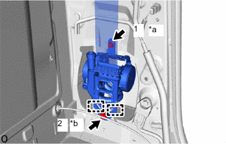
*a Bolt A *b Bolt B w/ Pretensioner:
-
Attach the 2 guides and temporarily install the rear No. 1 seat outer belt assembly LH with the 2 bolts.
-
Tighten the 2 bolts in the order shown in the illustration.
for Bolt A 12.5 N*m 127 kgf*cm 9 ft.*lbf for Bolt B 42.0 N*m 428 kgf*cm 31 ft.*lbf -
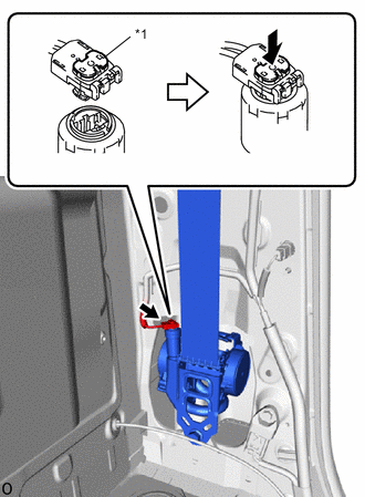
*1 Locking Button Connect the pretensioner connector and lock the locking button as shown in the illustration.
-
-
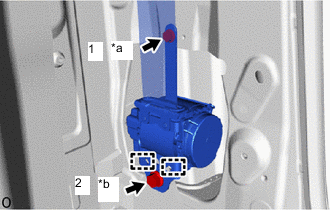
*a Bolt A *b Bolt B w/o Pretensioner:
-
Attach the 2 guides and install the rear No. 1 seat outer belt assembly LH with the 2 bolts.
-
Tighten the 2 bolts in the order shown in the illustration.
for Bolt A 12.5 N*m 127 kgf*cm 9 ft.*lbf for Bolt B 42.0 N*m 428 kgf*cm 31 ft.*lbf
-
-
Connect the shoulder anchor of the rear No. 1 seat outer belt assembly LH with the bolt.
42 N*m 428 kgf*cm 31 ft.*lbf -
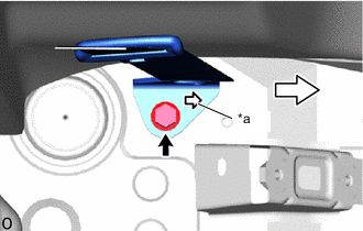
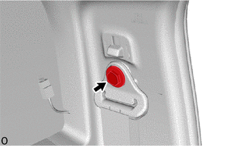
*a Mark 
Front Install the bolt and connect the floor anchor of the rear No. 1 seat outer belt assembly LH as shown in the illustration.
42 N*m 428 kgf*cm 31 ft.*lbf -
Check that the ELR locks.
Note:The check should be performed with the rear No. 1 seat outer belt assembly LH installed.
-
With the belt assembly installed, check that the belt locks when it is pulled out quickly.
-
-
- Click here
INSTALL LOWER QUARTER TRIM PANEL LH
- Click here
INSTALL SEAT BELT ANCHOR COVER CAP
- Click here
INSTALL FRONT DOOR SCUFF PLATE LH
- Click here
INSTALL REAR SEAT ASSEMBLY
-
for Seat Cushion 60/40 Split Type:
-
for Seat Cushion Bench Type:
-
- Click here
CONNECT CABLE TO NEGATIVE BATTERY TERMINAL
Note:When disconnecting the cable, some systems need to be initialized after the cable is reconnected.
- Click here
CHECK SRS WARNING LIGHT
-
for Type A:
-
for Type B:
-
for Type C:
-