SEAT BELT WARNING SYSTEM Driver Side Seat Belt Warning Light does not Operate
DESCRIPTION
When the ignition switch is turned to ON, the combination meter assembly receives a signal of the front seat inner belt assembly LH*1 or RH*2. If the driver side seat belt is not fastened, the combination meter assembly blinks the seat belt warning light. If the seat belt is fastened, the warning light goes off.
-
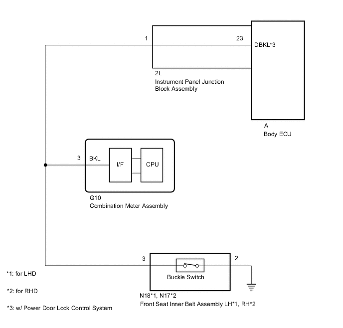
*1: for LHD
-
*2: for RHD
Tech Tips
The front seat belt warning light on the combination meter assembly is used for both the driver side seat and front passenger side seat.
WIRING DIAGRAM
CAUTION / NOTICE / HINT
Note
When replacing the combination meter assembly, make sure to replace it with a new one.
PROCEDURE
-
PERFORM ACTIVE TEST USING GTS (DRIVER SIDE SEAT BELT)
-
Connect the GTS to the DLC3.
-
Turn the ignition switch to ON.
-
Turn the GTS on.
-
Enter the following menus: Body Electrical / Combination Meter / Active Test.
-
Perform the Active Test according to the display on the GTS.
Body Electrical > Combination Meter > Active TestTester Display Measurement Item Control Range Diagnostic Note Driver Side Seat Belt Seat belt warning light OFF/ON -
Body Electrical > Combination Meter > Active TestTester Display Driver Side Seat Belt OK The seat belt warning light on the combination meter assembly operates normally. Result Proceed to OK NG
NG 
REPLACE COMBINATION METER ASSEMBLY Click here
OK 
-
-
READ VALUE USING GTS (DRIVER SIDE SEATBELT BUCKLE SWITCH)
-
Connect the GTS to the DLC3.
-
Turn the ignition switch to ON.
-
Turn the GTS on.
-
Enter the following menus: Body Electrical /Combination Meter / Data List.
-
Read the Data List according to the display on the GTS.
Body Electrical > Combination Meter > Data ListTester Display Measurement Item Range Normal Condition Diagnostic Note Driver Side Seatbelt Buckle Switch Driver side seat belt buckle switch signal ON or OFF ON: Driver side seat belt unfastened
OFF: Driver side seat belt fastened
-
Body Electrical > Combination Meter > Data ListTester Display Driver Side Seatbelt Buckle Switch Result Result Proceed to ON or OFF is displayed on the GTS screen according to the driver side seat belt condition A ON or OFF is not displayed normally on the GTS screen according to the driver side seat belt condition (for LHD) B ON or OFF is not displayed normally on the GTS screen according to the driver side seat belt condition (for RHD) C
A
REPLACE COMBINATION METER ASSEMBLY Click here
C 
INSPECT FRONT SEAT INNER BELT ASSEMBLY RH Click here
B
-
-
INSPECT FRONT SEAT INNER BELT ASSEMBLY LH
-
Remove the front seat inner belt assembly RH.
-
for Manual Seat:
-
for Power Seat:
-
-
Inspect the front seat inner belt assembly RH.
-
for Manual Seat:
-
for Power Seat:
Result Result Proceed to OK A NG (for Manual Seat) B NG (for Power Seat) C -
B
REPLACE FRONT SEAT INNER BELT ASSEMBLY LH Click here
C
REPLACE FRONT SEAT INNER BELT ASSEMBLY LH Click here
A
-
-
CHECK HARNESS AND CONNECTOR (FRONT SEAT INNER BELT ASSEMBLY LH - COMBINATION METER ASSEMBLY AND BODY GROUND)
-
Disconnect the N18 front seat inner belt assembly LH connector.
-
Disconnect the G10 combination meter assembly connector.
-
Disconnect the 2L instrument panel junction block assembly connector.
-
Measure the resistance according to the value(s) in the table below.
Standard Resistance Tester Connection Condition Specified Condition N18-3 - G10-3 (BKL) Always Below 1 Ω N18-2 - Body ground Always Below 1 Ω N18-3 or G10-3 (BKL) - Body ground Always 10 kΩ or higher Result Proceed to OK NG
OK
REPLACE COMBINATION METER ASSEMBLY Click here
NG
REPAIR OR REPLACE HARNESS OR CONNECTOR
-
-
INSPECT FRONT SEAT INNER BELT ASSEMBLY RH
-
Remove the front seat inner belt assembly RH.
-
for Manual Seat:
-
for Power Seat:
-
-
Inspect the front seat inner belt assembly RH.
-
for Manual Seat:
-
for Power Seat:
Result Result Proceed to OK A NG (for Manual Seat) B NG (for Power Seat) C -
B
REPLACE FRONT SEAT INNER BELT ASSEMBLY RH Click here
C
REPLACE FRONT SEAT INNER BELT ASSEMBLY RH Click here
A
-
-
CHECK HARNESS AND CONNECTOR (FRONT SEAT INNER BELT ASSEMBLY RH - COMBINATION METER ASSEMBLY AND BODY GROUND)
-
Disconnect the N17 front seat inner belt assembly RH connector.
-
Disconnect the G10 combination meter assembly connector.
-
Disconnect the 2L instrument panel junction block assembly connector.
-
Measure the resistance according to the value(s) in the table below.
Standard Resistance Tester Connection Condition Specified Condition N17-3 - G10-3 (BKL) Always Below 1 Ω N17-2 - Body ground Always Below 1 Ω N17-3 or G10-3 (BKL) - Body ground Always 10 kΩ or higher Result Proceed to OK NG
OK
REPLACE COMBINATION METER ASSEMBLY Click here
NG
REPAIR OR REPLACE HARNESS OR CONNECTOR
-