PRE-COLLISION SYSTEM Pre-collision System Cancel Switch Circuit
DESCRIPTION
Each time the pre-collision system cancel switch assembly is pressed, the multi-information display sensitivity setting display changes and the sensitivity of the pre-collision system changes between 3 levels. Also, when the switch is pressed and held, the pre-collision system cancels.
WIRING DIAGRAM
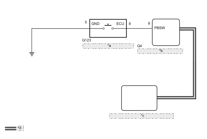
| *a | Pre-collision System Cancel Switch Assembly |
| *b | Forward Recognition Camera |
| *c | Millimeter Wave Radar Sensor Assembly |
| *d | CAN Communication Line |
CAUTION / NOTICE / HINT
Note
-
When the millimeter wave radar sensor assembly is replaced with a new one, adjustment of the radar sensor beam axis must be performed.
-
If the forward recognition camera has been replaced with a new one, be sure to perform Forward Recognition Axis Adjustment.
-
When a malfunction occurs in the communication line to the forward recognition camera, U023A and/or U1002 is output. If a DTC related to the CAN communication line is output, first troubleshoot the CAN communication line.
PROCEDURE
-
INSPECT PRE-COLLISION SYSTEM CANCEL SWITCH ASSEMBLY
-
Remove the pre-collision system cancel switch assembly.
-
Inspect the pre-collision system cancel switch assembly.
-
Install the pre-collision system cancel switch assembly.
Result Proceed to OK NG
NG 
REPLACE PRE-COLLISION SYSTEM CANCEL SWITCH ASSEMBLY Click here
OK 
-
-
CHECK HARNESS AND CONNECTOR (PRE-COLLISION SYSTEM CANCEL SWITCH ASSEMBLY - FORWARD RECOGNITION CAMERA AND BODY GROUND)
-
Disconnect the G123 pre-collision system cancel switch assembly connector.
-
Disconnect the Q4 forward recognition camera connector.
-
Measure the resistance according to the value(s) in the table below.
Standard Resistance Tester Connection Condition Specified Condition G123-8 (ECU) - Q4-9 (PBSW) Always Below 1 Ω G123-5 (GND) - Body ground Always Below 1 Ω G123-8 (ECU) or Q4-9 (PBSW) - Body ground Always 10 kΩ or higher -
Connect the Q4 forward recognition camera connector.
-
Connect the G123 pre-collision system cancel switch assembly connector.
Result Proceed to OK NG
NG
REPAIR OR REPLACE HARNESS OR CONNECTOR
OK
-
-
REPLACE FORWARD RECOGNITION CAMERA
-
Replace the forward recognition camera.
-
Perform Forward Recognition Axis Adjustment.
-
Operate the pre-collision system cancel switch assembly until it turns off.
-
Check the PCS warning light in the combination meter assembly.
OK The PCS warning light will illuminate. Result Proceed to OK NG
OK
END (FORWARD RECOGNITION CAMERA WAS DEFECTIVE)
NG
-
-
REPLACE MILLIMETER WAVE RADAR SENSOR ASSEMBLY
-
Replace the millimeter wave radar sensor assembly.
-
Adjust the millimeter wave radar sensor assembly.
-
Operate the pre-collision system cancel switch assembly until it turns off.
-
Check the PCS warning light in the combination meter assembly.
OK The PCS warning light will illuminate. Result Proceed to OK NG
OK
END (MILLIMETER WAVE RADAR SENSOR ASSEMBLY WAS DEFECTIVE)
NG
INSPECT METER / GAUGE SYSTEM Click here
-