Click here
-

CHECK MILLIMETER WAVE RADAR SENSOR
-
Measure the voltage and resistance according to the value(s) in the table below.
Tip:If the result is not as specified, there may be a malfunction on the wire harness side.
Terminal No. (Symbol) Wiring Color Terminal Description Condition Specified Condition A64-8 (IGB) - A64-1 (SGND) V - BR Power source Ignition switch ON 11 to 14 V*1
10.5 to 16 V*2
A64-1 (SGND) - Body ground BR - Body ground Ground Always Below 1 Ω *1: w/o Stop and Start System
*2: w/ Stop and Start System
-
Check for pulses according to the value(s) in the table below.
Terminal No. (Symbol) Wiring Color Terminal Description Condition Specified Condition A64-3 (CA2H) - A64-1 (SGND) R - BR CAN communication signal Ignition switch ON Pulse generation
(See waveform 1)
A64-2 (CA2L) - A64-1 (SGND) W - BR CAN communication signal Ignition switch ON Pulse generation
(See waveform 2)
A64-5 (CA1P) - A64-1 (SGND) B - BR CAN communication signal Ignition switch ON Pulse generation
(See waveform 1)
A64-6 (CA1N) - A64-1 (SGND) W - BR CAN communication signal Ignition switch ON Pulse generation
(See waveform 2)
-
WAVEFORM 1
-
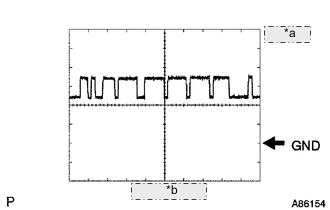
Table 1. *a 1 V/DIV. *b 10 μsec./DIV. CAN communication signal
Item Content Terminal Name Between A64-3 (CA2H) and A64-1 (SGND)
Between A64-5 (CA1P) and A64-1 (SGND)
Tester Range 1 V/DIV., 10 μsec./DIV. Condition Ignition switch ON Tip:The waveform varies depending on the CAN communication signal.
-
-
WAVEFORM 2
-
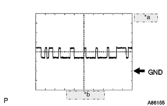
Table 2. *a 1 V/DIV. *b 10 μsec./DIV. CAN communication signal
Item Content Terminal Name Between A64-2 (CA2L) and A64-1 (SGND)
Between A64-6 (CA1N) and A64-1 (SGND)
Tester Range 1 V/DIV., 10 μsec./DIV. Condition Ignition switch ON Tip:The waveform varies depending on the CAN communication signal.
-
-
-

CHECK FORWARD RECOGNITION CAMERA
-
Measure the voltage and resistance according to the value(s) in the table below.
Tip:If the result is not as specified, there may be a malfunction on the wire harness side.
Terminal No. (Symbol) Wiring Color Terminal Description Condition Specified Condition Q4-8 (BZ) - Q4-10 (GND) R - B Skid control buzzer Ignition switch ON, skid control buzzer not operating 11 to 14 V Ignition switch ON, skid control buzzer operating 0 to 1.5 V Q4-9 (PBSW) - Q4-10 (GND) P - B Pre-collision system cancel switch assembly Pre-collision system cancel switch assembly being pressed Below 1 Ω Pre-collision system cancel switch assembly not being pressed 100 kΩ or higher Q4-7 (IGB) - Q4-10 (GND) V - B Power source Ignition switch ON 11 to 14 V*1 10.5 to 16 V*2 Ignition switch off Below 1 V Q4-10 (GND) - Body ground B - Body ground Ground Always Below 1 Ω *1: w/o Stop and Start System
*2: w/ Stop and Start System
-
Check for pulses according to the value(s) in the table below.
Terminal No. (Symbol) Wiring Color Terminal Description Condition Specified Condition Q4-5 (CA1P) - Q4-10 (GND) B - B CAN communication signal Ignition switch ON Pulse generation
(See waveform 1)
Q4-6 (CANH) - Q4-10 (GND) B - B CAN communication signal Ignition switch ON Pulse generation
(See waveform 1)
Q4-11 (CA1N) - Q4-10 (GND) V - B CAN communication signal Ignition switch ON Pulse generation
(See waveform 2)
Q4-12 (CANL) - Q4-10 (GND) BR - B CAN communication signal Ignition switch ON Pulse generation
(See waveform 2)
-
WAVEFORM 1
-
Table 3. *a 1 V/DIV. *b 10 μsec./DIV. CAN communication signal
Item Content Terminal Name Between Q4-5 (CA1P) - Q4-10 (GND)
Between Q4-6 (CANH) - Q4-10 (GND)
Tester Range 1 V/DIV., 10 μsec./DIV. Condition Ignition switch ON Tip:The waveform varies depending on the CAN communication signal.
-
-
WAVEFORM 2
-
Table 4. *a 1 V/DIV. *b 10 μsec./DIV. CAN communication signal
Item Content Terminal Name Between Q4-11 (CA1N) - Q4-10 (GND)
Between Q4-12 (CANL) - Q4-10 (GND)
Tester Range 1 V/DIV., 10 μsec./DIV. Condition Ignition switch ON Tip:The waveform varies depending on the CAN communication signal.
-
-