CAUTION / NOTICE / HINT
-
After turning the ignition switch off, waiting time may be required before disconnecting the cable from the negative (-) battery terminal. Therefore, make sure to read the disconnecting the cable from the negative (-) battery terminal notices before proceeding with work.
-
When disconnecting the cable from the negative (-) battery terminal while performing repairs, some systems need to be initialized after the cable is reconnected.
-
After replacing the airbag sensor assembly, refer to initialization*.
-
Inspect the fuses for circuits related to this system before performing the following inspection procedure.
-
When replacing the combination meter assembly, make sure to replace it with a new one.
PROCEDURE
- Click here
CHECK BATTERY
-
Measure the battery voltage.
Standard voltage 11 to 14 V Tip:
-
It may be possible to tell whether the battery is discharged by operating the horn.
-
If the voltage is below 11 V, recharge or replace the battery before proceeding to the next step.
Result Proceed to OK NG -
- OKClick here
- NG
REPLACE OR RECHARGE BATTERY
-
- Click here
CHECK CONNECTION OF CONNECTOR
-
Turn the ignition switch off.
-
Disconnect the cable from the negative (-) battery terminal, and wait for at least 90 seconds.
-
Check that the connector is properly connected to the combination meter assembly.
Result Proceed to The connector is properly connected The connector is not properly connected
- The connector is properly connectedClick here
- The connector is not properly connected
CONNECT CONNECTOR PROPERLY
-
- Click here
CHECK HARNESS AND CONNECTOR (COMBINATION METER ASSEMBLY - BATTERY AND BODY GROUND)
-
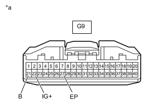
*a Front view of wire harness connector
(to Combination Meter Assembly)
Disconnect the cable from the negative (-) battery terminal, and wait for at least 90 seconds.
-
Disconnect the connector from the combination meter assembly.
-
Connect the cable to the negative (-) battery terminal, and wait for at least 2 seconds.
-
Turn the ignition switch to ON.
-
Measure the voltage according to the value(s) in the table below.
Standard Voltage Tester Connection Condition Specified Condition G9-22 (IG+) - Body ground Ignition switch ON 11 to 14 V G9-21 (B) - Body ground Always 11 to 14 V -
Measure the resistance according to the value(s) in the table below.
Standard Resistance Tester Connection Condition Specified Condition G9-27 (EP) - Body ground Always Below 1 Ω Result Proceed to OK NG
- OKClick here
- NG
REPAIR OR REPLACE HARNESS OR CONNECTOR
-
- Click here
CHECK SRS WARNING LIGHT (SHORT TO GROUND)
-
Turn the ignition switch off.
-
Disconnect the cable from the negative (-) battery terminal, and wait for at least 90 seconds.
-
Connect the connector to the combination meter assembly.
-
Connect the cable to the negative (-) battery terminal, and wait for at least 2 seconds.
-
Turn the ignition switch to ON.
-
Check the SRS warning light condition.
OK After the primary check period, the SRS warning light goes off for approximately 10 seconds and then remains on. Tip:The primary check period is approximately 6 seconds after the ignition switch is turned to ON.
Result Proceed to OK NG
- OK
REPLACE AIRBAG SENSOR ASSEMBLYClick here
- NG
GO TO METER / GAUGE SYSTEMClick here
-