| DTC Code | DTC Name |
|---|---|
| Speed Signal Circuit |
DESCRIPTION
The vehicle speed signal consists of pulses sent to the combination meter assembly from the speedometer sensor*1 or brake actuator assembly (skid control ECU)*2.
-
*1: w/o ABS
*2: w/ ABS
CAUTION / NOTICE / HINT
-
When replacing the combination meter assembly, make sure to replace it with a new one.
-
Depending on the parts that are replaced during vehicle inspection or maintenance, performing initialization, registration or calibration may be needed.
-
w/ Entry and Start System:
Before replacing the certification ECU (smart key ECU assembly), refer to the smart entry and start system.
-
w/ Audio and Visual System (for Radio and Display Type):
When replacing the radio and display receiver assembly, it is necessary to perform the vehicle contract setting for Connected Services.
-
If the body ECU has been replaced, it is necessary to initialize the body ECU.
PROCEDURE
- Click here
CHECK CERTIFICATION ECU (SMART KEY ECU ASSEMBLY)
Note:For vehicles without an entry and start system, go to "Check Body ECU".
-
*1: for 1GR-FE
-
*2: for 1TR-FE, 2TR-FE
-
*3: for 1GD-FTV, 2GD-FTV
-
*4: for 2KD-FTV
-
*5: w/ Body ECU
-
*6: w/ Navigation System
-
*7: w/ Audio and Visual System (for Radio and Display Type)
-
*8: w/ Audio and Visual System (for Radio Receiver Type)
-
*9: for 5L-E
-
*10: w/ Telematics System
-
*a Rear view of wire harness connector
(to Combination Meter Assembly)
Disconnect the combination meter assembly connector.
-
Disconnect the G88*1, G45*2, G85*3, G83*4 or G120*9 ECM connector.
-
Disconnect the G27 body ECU connector.*5
-
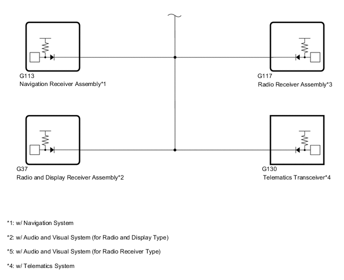
Disconnect the G113 navigation receiver assembly connector.*6
-
Disconnect the G37 radio and display receiver assembly connector.*7
-
Disconnect the G117 radio receiver assembly connector.*8
-
Disconnect the G130 telematics transceiver connector.*10
-
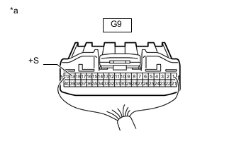
Measure the voltage according to the value(s) in the table below.
Standard Voltage Tester Connection Switch Condition Specified Condition G9-19 (+S) - Body ground Ignition switch ON 4.5 to 14 V Result Proceed to OK NG
- OKClick here
- NGClick here
-
- Click here
CHECK BODY ECU
Note:For vehicles without a body ECU, go to "Check TCM".
-
*1: for 1GR-FE
-
*2: for 1TR-FE, 2TR-FE
-
*3: for 1GD-FTV, 2GD-FTV
-
*4: for 2KD-FTV
-
*5: w/ Entry and Start System
-
*6: w/ Navigation System
-
*7: w/ Audio and Visual System (for Radio and Display Type)
-
*8: w/ Audio and Visual System (for Radio Receiver Type)
-
*9: for 5L-E
-
*10: w/ Telematics System
-
*a Rear view of wire harness connector
(to Combination Meter Assembly)
Disconnect the combination meter assembly connector.
-
Disconnect the G88*1, G45*2, G85*3, G83*4 or G120*9 ECM connector.
-
Disconnect the G69 certification ECU (smart key ECU assembly) connector.*5
-
Disconnect the G113 navigation receiver assembly connector.*6
-
Disconnect the G37 radio and display receiver assembly connector.*7
-
Disconnect the G117 radio receiver assembly connector.*8
-
Disconnect the G130 telematics transceiver connector.*10
-
Measure the voltage according to the value(s) in the table below.
Standard Voltage Tester Connection Switch Condition Specified Condition G9-19 (+S) - Body ground Ignition switch ON 4.5 to 14 V Result Proceed to OK NG
- OKClick here
- NGClick here
-
- Click here
CHECK NAVIGATION RECEIVER ASSEMBLY
Note:For vehicles without a navigation system, go to "Check Radio and Display Receiver Assembly".
-
*1: for 1GR-FE
-
*2: for 1TR-FE, 2TR-FE
-
*3: for 1GD-FTV, 2GD-FTV
-
*4: for 2KD-FTV
-
*5: w/ Entry and Start System
-
*6: w/ Body ECU
-
*7: for 5L-E
-
*8: w/ Telematics System
-
*a Rear view of wire harness connector
(to Combination Meter Assembly)
Disconnect the combination meter assembly connector.
-
Disconnect the G88*1, G45*2, G85*3, G83*4 or G120*7 ECM connector.
-
Disconnect the G69 certification ECU (smart key ECU assembly) connector.*5
-
Disconnect the G27 body ECU connector.*6
-
Disconnect the G130 telematics transceiver connector.*8
-
Measure the voltage according to the value(s) in the table below.
Standard Voltage Tester Connection Switch Condition Specified Condition G9-19 (+S) - Body ground Ignition switch ON 4.5 to 14 V Result Proceed to OK NG
- OKClick here
- NGClick here
-
- Click here
CHECK RADIO AND DISPLAY RECEIVER ASSEMBLY
Note:For vehicles without an audio and visual system (for radio and display type), go to "Check Radio Receiver Assembly".
-
*1: for 1GR-FE
-
*2: for 1TR-FE, 2TR-FE
-
*3: for 1GD-FTV, 2GD-FTV
-
*4: for 2KD-FTV
-
*5: w/ Entry and Start System
-
*6: w/ Body ECU
-
*7: for 5L-E
-
*8: w/ Telematics System
-
*a Rear view of wire harness connector
(to Combination Meter Assembly)
Disconnect the combination meter assembly connector.
-
Disconnect the G88*1, G45*2, G85*3 G83*4 or G120*7 ECM connector.
-
Disconnect the G69 certification ECU (smart key ECU assembly) connector.*5
-
Disconnect the G27 body ECU connector.*6
-
Disconnect the G130 telematics transceiver connector.*8
-
Measure the voltage according to the value(s) in the table below.
Standard Voltage Tester Connection Switch Condition Specified Condition G9-19 (+S) - Body ground Ignition switch ON 4.5 to 14 V Result Proceed to OK NG
- OKClick here
- NGClick here
-
- Click here
CHECK RADIO RECEIVER ASSEMBLY
Note:For vehicles without an audio and visual system (for radio receiver type), go to "Check ECM".
-
*1: for 1GR-FE
-
*2: for 1TR-FE, 2TR-FE
-
*3: for 1GD-FTV, 2GD-FTV
-
*4: for 2KD-FTV
-
*5: w/ Entry and Start System
-
*6: w/ Body ECU
-
*7: for 5L-E
-
*8: w/ Telematics System
-
*a Rear view of wire harness connector
(to Combination Meter Assembly)
Disconnect the combination meter assembly connector.
-
Disconnect the G88*1, G45*2, G85*3, G83*4 or G120*7 ECM connector.
-
Disconnect the G69 certification ECU (smart key ECU assembly) connector.*5
-
Disconnect the G27 body ECU connector.*6
-
Disconnect the G130 telematics transceiver connector.*8
-
Measure the voltage according to the value(s) in the table below.
Standard Voltage Tester Connection Switch Condition Specified Condition G9-19 (+S) - Body ground Ignition switch ON 4.5 to 14 V Result Proceed to OK NG
- OKClick here
- NGClick here
-
- Click here
CHECK ECM
-
*1: w/ Entry and Start System
-
*2: w/ Body ECU
-
*3: w/ Navigation System
-
*4: w/ Audio and Visual System (for Radio and Display Type)
-
*5: w/ Audio and Visual System (for Radio Receiver Type)
-
*6: w/ Telematics System
-
*a Rear view of wire harness connector
(to Combination Meter Assembly)
Disconnect the combination meter assembly connector.
-
Disconnect the G69 certification ECU (smart key ECU assembly) connector.*1
-
Disconnect the G27 body ECU connector.*2
-
Disconnect the G113 navigation receiver assembly connector.*3
-
Disconnect the G37 radio and display receiver assembly connector.*4
-
Disconnect the G117 radio receiver assembly connector.*5
-
Disconnect the G130 telematics transceiver connector.*6
-
Measure the voltage according to the value(s) in the table below.
Standard Voltage Tester Connection Switch Condition Specified Condition G9-19 (+S) - Body ground Ignition switch ON 4.5 to 14 V Result Proceed to OK NG
- OKClick here
- NGClick here
-
- Click here
CHECK TELEMATICS TRANSCEIVER
Note:For vehicles without a telematics system, go to "Check Veicle Type"
-
*1: for 2TR-FE
-
*2: for 1GD-FTV, 2GD-FTV
-
*3: w/ Entry and Start System
-
*4: w/ Body ECU
-
*5: w/ Audio and Visual System (for Radio and Display Type)
-
*6: w/ Audio and Visual System (for Radio Receiver Type)
-
*a Rear view of wire harness connector
(to Combination Meter Assembly)
Disconnect the combination meter assembly connector.
-
Disconnect the G45*1, G85*2, ECM connector.
-
Disconnect the G69 certification ECU (smart key ECU assembly) connector.*3
-
Disconnect the G27 body ECU connector.*4
-
Disconnect the G37 radio and display receiver assembly connector.*5
-
Disconnect the G117 radio receiver assembly connector.*6
-
Measure the voltage according to the value(s) in the table below.
Standard Voltage Tester Connection Switch Condition Specified Condition G9-19 (+S) - Body ground Ignition switch ON 4.5 to 14 V Result Proceed to OK NG
- OKClick here
- NGClick here
-
- Click here
CHECK VEHICLE TYPE
-
Check vehicle type.
Result Result Proceed to w/ ABS A w/o ABS B
-
- Click here
CHECK COMBINATION METER ASSEMBLY (OUTPUT VOLTAGE)
-
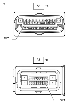
*A w/ VSC *B w/o VSC *a Front view of wire harness connector
(to Brake Actuator Assembly [Skid Control ECU])
Disconnect the brake actuator assembly (skid control ECU) connector.
-
Measure the voltage according to the value(s) in the table below.
Standard Voltage Table 1. w/ VSC Tester Connection Switch Condition Specified Condition A4-14 (SP1) - Body ground Ignition switch ON 11 to 14 V Table 2. w/o VSC Tester Connection Switch Condition Specified Condition A3-22 (SP1) - Body ground Ignition switch ON 11 to 14 V Result Proceed to OK NG
- OKClick here
- NGClick here
-
- Click here
CHECK COMBINATION METER ASSEMBLY (INPUT WAVEFORM)
-
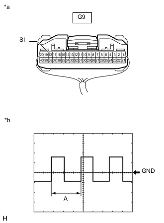
*a Component with harness connected
(Combination Meter Assembly)
*b Waveform Remove the combination meter assembly with the connector(s) still connected.
-
Connect an oscilloscope to terminal G9-18 (SI) and body ground.
-
Check the signal waveform according to the condition(s) in the table below.
Table 3. Measurement Condition Item Condition Tester Connection G9-18 (SI) - Body ground Tool Setting 5 V/DIV, 20 ms./DIV Vehicle Condition Driving at approximately 20 km/h (12 mph) Tip:When the system is functioning normally, one wheel revolution generates 4 pulses. As the vehicle speed increases, the width indicated by A in the illustration narrows.
OK The waveform displayed is as shown in the illustration. Result Proceed to OK NG
- OK
REPLACE COMBINATION METER ASSEMBLYClick here
- NG
REPLACE BRAKE ACTUATOR ASSEMBLY (SKID CONTROL ECU) w/ VSC:Click here
REPLACE BRAKE ACTUATOR ASSEMBLY (SKID CONTROL ECU) w/o VSC:Click here
-
- Click here
CHECK HARNESS AND CONNECTOR (COMBINATION METER ASSEMBLY - CERTIFICATION ECU [SMART KEY ECU ASSEMBLY])
-
*1: for 1GR-FE
-
*2: for 1TR-FE, 2TR-FE
-
*3: for 1GD-FTV, 2GD-FTV
-
*4: for 2KD-FTV
-
*5: w/ Body ECU
-
*6: w/ Navigation System
-
*7: w/ Audio and Visual System (for Radio and Display Type)
-
*8: w/ Audio and Visual System (for Radio Receiver Type)
-
*9: for 5L-E
-
*10: w/ Telematics System
-
Disconnect the G9 combination meter assembly connector.
-
Disconnect the G88*1, G45*2, G85*3, G83*4 or G120*9 ECM connector.
-
Disconnect the G69 certification ECU (smart key ECU assembly) connector.
-
Disconnect the G27 body ECU connector.*5
-
Disconnect the G113 navigation receiver assembly connector.*6
-
Disconnect the G37 radio and display receiver assembly connector.*7
-
Disconnect the G117 radio receiver assembly connector.*8
-
Disconnect the G130 telematics transceiver connector.*10
-
Measure the resistance according to the value(s) in the table below.
Standard Resistance Tester Connection Condition Specified Condition G9-19 (+S) - G69-7 (SPD) Always Below 1 Ω G9-19 (+S) or G69-7 (SPD) - Body ground Always 10 kΩ or higher Result Proceed to OK NG
- OK
REPLACE CERTIFICATION ECU (SMART KEY ECU ASSEMBLY)
- NG
REPAIR OR REPLACE HARNESS OR CONNECTOR
-
- Click here
CHECK HARNESS AND CONNECTOR (COMBINATION METER ASSEMBLY - BODY ECU)
-
*1: for 1GR-FE
-
*2: for 1TR-FE, 2TR-FE
-
*3: for 1GD-FTV, 2GD-FTV
-
*4: for 2KD-FTV
-
*5: w/ Entry and Start System
-
*6: w/ Navigation System
-
*7: w/ Audio and Visual System (for Radio and Display Type)
-
*8: w/ Audio and Visual System (for Radio Receiver Type)
-
*9: for 5L-E
-
*10: w/ Telematics System
-
Disconnect the G9 combination meter assembly connector.
-
Disconnect the G88*1, G45*2, G85*3, G83*4 or G120*9 ECM connector.
-
Disconnect the G69 certification ECU (smart key ECU assembly) connector.*5
-
Disconnect the G27 body ECU connector.
-
Disconnect the G113 navigation receiver assembly connector.*6
-
Disconnect the G37 radio and display receiver assembly connector.*7
-
Disconnect the G117 radio receiver assembly connector.*8
-
Disconnect the G130 telematics transceiver connector.*10
-
Measure the resistance according to the value(s) in the table below.
Standard Resistance Tester Connection Condition Specified Condition G9-19 (+S) - G27-5 (SPD) Always Below 1 Ω G9-19 (+S) or G27-5 (SPD) - Body ground Always 10 kΩ or higher Result Proceed to OK NG
- OK
REPLACE BODY ECU for LHD:Click here
REPLACE BODY ECU for RHD:Click here
- NG
REPAIR OR REPLACE HARNESS OR CONNECTOR
-
- Click here
CHECK HARNESS AND CONNECTOR (COMBINATION METER ASSEMBLY - NAVIGATION RECEIVER ASSEMBLY)
-
*1: for 1GR-FE
-
*2: for 1TR-FE, 2TR-FE
-
*3: for 1GD-FTV, 2GD-FTV
-
*4: for 2KD-FTV
-
*5: w/ Entry and Start System
-
*6: w/ Body ECU
-
*7: for 5L-E
-
*8: w/ Telematics System
-
Disconnect the G9 combination meter assembly connector.
-
Disconnect the G88*1, G45*2, G85*3, G83*4 or G120*7 ECM connector.
-
Disconnect the G69 certification ECU (smart key ECU assembly) connector.*5
-
Disconnect the G27 body ECU connector.*6
-
Disconnect the G113 navigation receiver assembly connector.
-
Disconnect the G130 telematics transceiver connector.*8
-
Measure the resistance according to the value(s) in the table below.
Standard Resistance Tester Connection Condition Specified Condition G9-19 (+S) - G113-17 (SPD) Always Below 1 Ω G9-19 (+S) or G113-17 (SPD) - Body ground Always 10 kΩ or higher Result Proceed to OK NG
- OK
REPLACE NAVIGATION RECEIVER ASSEMBLYClick here
- NG
REPAIR OR REPLACE HARNESS OR CONNECTOR
-
- Click here
CHECK HARNESS AND CONNECTOR (COMBINATION METER ASSEMBLY - RADIO AND DISPLAY RECEIVER ASSEMBLY)
-
*1: for 1GR-FE
-
*2: for 1TR-FE, 2TR-FE
-
*3: for 1GD-FTV, 2GD-FTV
-
*4: for 2KD-FTV
-
*5: w/ Entry and Start System
-
*6: w/ Body ECU
-
*7: for 5L-E
-
*8: w/ Telematics System
-
Disconnect the G9 combination meter assembly connector.
-
Disconnect the G88*1, G45*2, G85*3, G83*4 or G120*7 ECM connector.
-
Disconnect the G69 certification ECU (smart key ECU assembly) connector.*5
-
Disconnect the G27 body ECU connector.*6
-
Disconnect the G37 radio and display receiver assembly connector.
-
Disconnect the G130 telematics transceiver connector.*8
-
Measure the resistance according to the value(s) in the table below.
Standard Resistance Tester Connection Condition Specified Condition G9-19 (+S) - G37-17 (SPD) Always Below 1 Ω G9-19 (+S) or G37-17 (SPD) - Body ground Always 10 kΩ or higher Result Proceed to OK NG
- OK
REPLACE RADIO AND DISPLAY RECEIVER ASSEMBLYClick here
- NG
REPAIR OR REPLACE HARNESS OR CONNECTOR
-
- Click here
CHECK HARNESS AND CONNECTOR (COMBINATION METER ASSEMBLY - RADIO RECEIVER ASSEMBLY)
-
*1: for 1GR-FE
-
*2: for 1TR-FE, 2TR-FE
-
*3: for 1GD-FTV, 2GD-FTV
-
*4: for 2KD-FTV
-
*5: w/ Entry and Start System
-
*6: w/ Body ECU
-
*7: for 5L-E
-
*8: w/ Telematics System
-
Disconnect the G9 combination meter assembly connector.
-
Disconnect the G88*1, G45*2, G85*3, G83*4 or G120*7 ECM connector.
-
Disconnect the G69 certification ECU (smart key ECU assembly) connector.*5
-
Disconnect the G27 body ECU connector.*6
-
Disconnect the G117 radio receiver assembly connector.
-
Disconnect the G130 telematics transceiver connector.*8
-
Measure the resistance according to the value(s) in the table below.
Standard Resistance Tester Connection Condition Specified Condition G9-19 (+S) - G117-17 (SPD) Always Below 1 Ω G9-19 (+S) or G117-17 (SPD) - Body ground Always 10 kΩ or higher Result Proceed to OK NG
- OK
REPLACE RADIO RECEIVER ASSEMBLYClick here
- NG
REPAIR OR REPLACE HARNESS OR CONNECTOR
-
- Click here
CHECK HARNESS AND CONNECTOR (COMBINATION METER ASSEMBLY - ECM)
-
*1: for 1GR-FE
-
*2: for 1TR-FE, 2TR-FE
-
*3: for 1GD-FTV, 2GD-FTV
-
*4: for 2KD-FTV
-
*5: w/ Entry and Start System
-
*6: w/ Body ECU
-
*7: w/ Navigation System
-
*8: w/ Audio and Visual System (for Radio and Display Type)
-
*9: w/ Audio and Visual System (for Radio Receiver Type)
-
*10: for 5L-E
-
*11: w/ Telematics System
-
Disconnect the G9 combination meter assembly connector.
-
Disconnect the G88*1, G45*2, G85*3, G83*4 or G120*10 ECM connector.
-
Disconnect the G69 certification ECU (smart key ECU assembly) connector.*5
-
Disconnect the G27 body ECU connector.*6
-
Disconnect the G113 navigation receiver assembly connector.*7
-
Disconnect the G37 radio and display receiver assembly connector.*8
-
Disconnect the G117 radio receiver assembly connector.*9
-
Disconnect the G130 telematics transceiver connector.*11
-
Measure the resistance according to the value(s) in the table below.
Standard Resistance Table 4. for 1GR-FE Tester Connection Condition Specified Condition G9-19 (+S) - G88-12 (SPD) Always Below 1 Ω G9-19 (+S) or G88-12 (SPD) - Body ground Always 10 kΩ or higher Table 5. for 1TR-FE, 2TR-FE Tester Connection Condition Specified Condition G9-19 (+S) - G45-23 (SPD) Always Below 1 Ω G9-19 (+S) or G45-23 (SPD) - Body ground Always 10 kΩ or higher Table 6. for 1GD-FTV, 2GD-FTV Tester Connection Condition Specified Condition G9-19 (+S) - G85-10 (SPD) Always Below 1 Ω G9-19 (+S) or G85-10 (SPD) - Body ground Always 10 kΩ or higher Table 7. for 2KD-FTV Tester Connection Condition Specified Condition G9-19 (+S) - G83-17 (SPD) Always Below 1 Ω G9-19 (+S) or G83-17 (SPD) - Body ground Always 10 kΩ or higher Table 8. for 5L-E Tester Connection Condition Specified Condition G9-19 (+S) - G120-25 (SP1) Always Below 1 Ω G9-19 (+S) or G120-25 (SP1) - Body ground Always 10 kΩ or higher Result Proceed to OK NG
- OK
REPLACE ECM for 1GR-FE:Click here
REPLACE ECM for 1TR-FE:Click here
REPLACE ECM for 2TR-FE:Click here
REPLACE ECM for 1GD-FTV:Click here
REPLACE ECM for 2GD-FTV:Click here
REPLACE ECM for 2KD-FTV:Click here
REPLACE ECM for 5L-E:Click here
- NG
REPAIR OR REPLACE HARNESS OR CONNECTOR
-
- Click here
CHECK HARNESS AND CONNECTOR (COMBINATION METER ASSEMBLY - TELEMATICS TRANSCEIVER)
-
*1: for 2TR-FE
-
*2: for 1GD-FTV, 2GD-FTV
-
*3: w/ Entry and Start System
-
*4: w/ Body ECU
-
*5: w/ Audio and Visual System (for Radio and Display Type)
-
*6: w/ Audio and Visual System (for Radio Receiver Type)
-
Disconnect the G9 combination meter assembly connector.
-
Disconnect the G45*1 or G85*2 ECM connector.
-
Disconnect the G69 certification ECU (smart key ECU assembly) connector.*3
-
Disconnect the G27 body ECU connector.*4
-
Disconnect the G37 radio and display receiver assembly connector.*5
-
Disconnect the G117 radio receiver assembly connector.*6
-
Disconnect the G130 telematics transceiver connector.
-
Measure the resistance according to the value(s) in the table below.
Standard Resistance Tester Connection Condition Specified Condition G9-19 (+S) - G130-10 (SPDP) Always Below 1 Ω G9-19 (+S) or G130-10 (SPDP) - Body ground Always 10 kΩ or higher Result Proceed to OK NG
- OK
REPLACE TELEMATICS TRANSCEIVERClick here
- NG
REPAIR OR REPLACE HARNESS OR CONNECTOR
-
- Click here
CHECK COMBINATION METER ASSEMBLY (INPUT WAVEFORM)
-
*a Component with harness connected
(Combination Meter Assembly)
*b Waveform Remove the combination meter assembly with the connector(s) still connected.
-
Connect an oscilloscope to terminal G9-18 (SI) and body ground.
-
Check the signal waveform according to the condition(s) in the table below.
Table 9. Measurement Condition Item Condition Tester Connection G9-18 (SI) - Body ground Tool Setting 5 V/DIV, 20 ms./DIV Vehicle Condition Driving at approximately 20 km/h (12 mph) Tip:When the system is functioning normally, one wheel revolution generates 4 pulses. As the vehicle speed increases, the width indicated by A in the illustration narrows.
OK The waveform displayed is as shown in the illustration. Result Proceed to OK NG
- OK
REPLACE COMBINATION METER ASSEMBLYClick here
- NGClick here
-
- Click here
CHECK HARNESS AND CONNECTOR (COMBINATION METER ASSEMBLY - BRAKE ACTUATOR ASSEMBLY [SKID CONTROL ECU])
-
Disconnect the G9 combination meter assembly connector.
-
Disconnect the A4*1 or A3*2 brake actuator assembly (skid control ECU) connector.
-
*1: w/ VSC
-
*2: w/o VSC
-
-
Measure the resistance according to the value(s) in the table below.
Standard Resistance Table 10. w/ VSC Tester Connection Condition Specified Condition G9-18 (SI) - A4-14 (SP1) Always Below 1 Ω G9-18 (SI) or A4-14 (SP1) - Body ground Always 10 kΩ or higher Table 11. w/o VSC Tester Connection Condition Specified Condition G9-18 (SI) - A3-22 (SP1) Always Below 1 Ω G9-18 (SI) or A3-22 (SP1) - Body ground Always 10 kΩ or higher Result Proceed to OK NG
- OK
REPLACE COMBINATION METER ASSEMBLYClick here
- NG
REPAIR OR REPLACE HARNESS OR CONNECTOR
-
- Click here
CHECK HARNESS AND CONNECTOR (SPEEDOMETER SENSOR - COMBINATION METER ASSEMBLY AND BODY GROUND)
-
Disconnect the C62 speedometer sensor connector.
-
Disconnect the G9 and G10 combination meter assembly connectors.
-
Measure the resistance according to the value (s) in the table below.
Standard Resistance Tester Connection Condition Specified Condition C62-3 (SI) - G9-18 (SI) Always Below 1 Ω C62-3 (SI) or G9-18 (SI) - Body ground Always 10 kΩ or higher Result Proceed to OK NG
- OK
REPLACE SPEEDOMETER SENSORClick here
- NG
REPAIR OR REPLACE HARNESS OR CONNECTOR
-