METER / GAUGE SYSTEM Speed Signal Circuit
DESCRIPTION
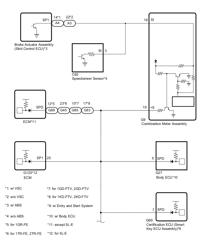
The vehicle speed signal consists of pulses sent to the combination meter assembly from the speedometer sensor*1 or brake actuator assembly (skid control ECU)*2.
-
*1: w/o ABS
*2: w/ ABS
WIRING DIAGRAM
CAUTION / NOTICE / HINT
Note
-
When replacing the combination meter assembly, make sure to replace it with a new one.
-
Depending on the parts that are replaced during vehicle inspection or maintenance, performing initialization, registration or calibration may be needed.
-
w/ Entry and Start System:
Before replacing the certification ECU (smart key ECU assembly), refer to the smart entry and start system.
-
w/ Audio and Visual System (for Radio and Display Type):
When replacing the radio and display receiver assembly, it is necessary to perform the vehicle contract setting for Connected Services.
-
If the body ECU has been replaced, it is necessary to initialize the body ECU.
PROCEDURE
-
CHECK CERTIFICATION ECU (SMART KEY ECU ASSEMBLY)
Note
For vehicles without an entry and start system, go to "Check Body ECU".
-
*1: for 1GR-FE
-
*2: for 1TR-FE, 2TR-FE
-
*3: for 1GD-FTV, 2GD-FTV
-
*4: for 1KD-FTV, 2KD-FTV
-
*5: w/ Body ECU
-
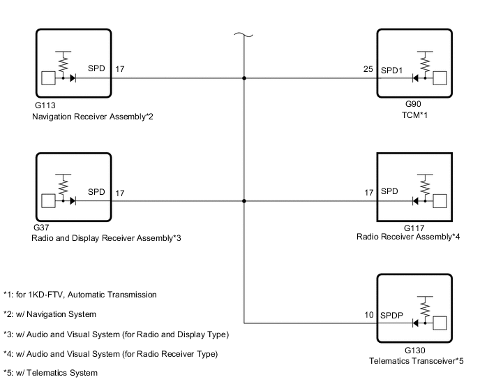
*6: for 1KD-FTV, Automatic Transmission
-
*7: w/ Navigation System
-
*8: w/ Audio and Visual System (for Radio and Display Type)
-
*9: w/ Audio and Visual System (for Radio Receiver Type)
-
*10: for 5L-E
-
*11: w/ Telematics System
-
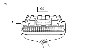
*a Rear view of wire harness connector
(to Combination Meter Assembly)
Disconnect the combination meter assembly connector.
-
Disconnect the G88*1, G45*2, G85*3, G83*4 or G120*10 ECM connector.
-
Disconnect the G27 body ECU connector.*5
-
Disconnect the G90 TCM connector.*6
-
Disconnect the G113 navigation receiver assembly connector.*7
-
Disconnect the G37 radio and display receiver assembly connector.*8
-
Disconnect the G117 radio receiver assembly connector.*9
-
Disconnect the G130 telematics transceiver connector.*11
-
Measure the voltage according to the value(s) in the table below.
Standard Voltage Tester Connection Switch Condition Specified Condition G9-19 (+S) - Body ground Ignition switch ON 4.5 to 14 V Result Proceed to OK NG
NG 
CHECK HARNESS AND CONNECTOR (COMBINATION METER ASSEMBLY - CERTIFICATION ECU [SMART KEY ECU ASSEMBLY]) Click here
OK 
-
-
CHECK BODY ECU
Note
For vehicles without a body ECU, go to "Check TCM".
-
*1: for 1GR-FE
-
*2: for 1TR-FE, 2TR-FE
-
*3: for 1GD-FTV, 2GD-FTV
-
*4: for 1KD-FTV, 2KD-FTV
-
*5: w/ Entry and Start System
-
*6: for 1KD-FTV, Automatic Transmission
-
*7: w/ Navigation System
-
*8: w/ Audio and Visual System (for Radio and Display Type)
-
*9: w/ Audio and Visual System (for Radio Receiver Type)
-
*10: for 5L-E
-
*11: w/ Telematics System
-
*a Rear view of wire harness connector
(to Combination Meter Assembly)
Disconnect the combination meter assembly connector.
-
Disconnect the G88*1, G45*2, G85*3, G83*4 or G120*10 ECM connector.
-
Disconnect the G69 certification ECU (smart key ECU assembly) connector.*5
-
Disconnect the G90 TCM connector.*6
-
Disconnect the G113 navigation receiver assembly connector.*7
-
Disconnect the G37 radio and display receiver assembly connector.*8
-
Disconnect the G117 radio receiver assembly connector.*9
-
Disconnect the G130 telematics transceiver connector.*11
-
Measure the voltage according to the value(s) in the table below.
Standard Voltage Tester Connection Switch Condition Specified Condition G9-19 (+S) - Body ground Ignition switch ON 4.5 to 14 V Result Proceed to OK NG
NG
CHECK HARNESS AND CONNECTOR (COMBINATION METER ASSEMBLY - BODY ECU) Click here
OK
-
-
CHECK TCM
Note
For vehicles without a KD series engine, automatic transmission, go to "Check Navigation Receiver Assembly".
-
*1: w/ Entry and Start System
-
*2: w/ Body ECU
-
*3: w/ Navigation System
-
*4: w/ Audio and Visual System (for Radio and Display Type)
-
*5: w/ Audio and Visual System (for Radio Receiver Type)
-
*6: w/ Telematics System
-
*a Rear view of wire harness connector
(to Combination Meter Assembly)
Disconnect the combination meter assembly connector.
-
Disconnect the G83 ECM connector.
-
Disconnect the G69 certification ECU (smart key ECU assembly) connector.*1
-
Disconnect the G27 body ECU connector.*2
-
Disconnect the G113 navigation receiver assembly connector.*3
-
Disconnect the G37 radio and display receiver assembly connector.*4
-
Disconnect the G117 radio receiver assembly connector.*5
-
Disconnect the G130 telematics transceiver connector.*6
-
Measure the voltage according to the value(s) in the table below.
Standard Voltage Tester Connection Switch Condition Specified Condition G9-19 (+S) - Body ground Ignition switch ON 4.5 to 14 V Result Proceed to OK NG
NG
CHECK HARNESS AND CONNECTOR (COMBINATION METER ASSEMBLY - TCM) Click here
OK
-
-
CHECK NAVIGATION RECEIVER ASSEMBLY
Note
For vehicles without a navigation system, go to "Check Radio and Display Receiver Assembly".
-
*1: for 1GR-FE
-
*2: for 1TR-FE, 2TR-FE
-
*3: for 1GD-FTV, 2GD-FTV
-
*4: for 1KD-FTV, 2KD-FTV
-
*5: w/ Entry and Start System
-
*6: w/ Body ECU
-
*7: for 1KD-FTV, Automatic Transmission
-
*8: for 5L-E
-
*9: w/ Telematics System
-
*a Rear view of wire harness connector
(to Combination Meter Assembly)
Disconnect the combination meter assembly connector.
-
Disconnect the G88*1, G45*2, G85*3, G83*4 or G120*8 ECM connector.
-
Disconnect the G69 certification ECU (smart key ECU assembly) connector.*5
-
Disconnect the G27 body ECU connector.*6
-
Disconnect the G90 TCM connector.*7
-
Disconnect the G130 telematics transceiver connector.*9
-
Measure the voltage according to the value(s) in the table below.
Standard Voltage Tester Connection Switch Condition Specified Condition G9-19 (+S) - Body ground Ignition switch ON 4.5 to 14 V Result Proceed to OK NG
NG
CHECK HARNESS AND CONNECTOR (COMBINATION METER ASSEMBLY - NAVIGATION RECEIVER ASSEMBLY) Click here
OK
-
-
CHECK RADIO AND DISPLAY RECEIVER ASSEMBLY
Note
For vehicles without an audio and visual system (for radio and display type), go to "Check Radio Receiver Assembly".
-
*1: for 1GR-FE
-
*2: for 1TR-FE, 2TR-FE
-
*3: for 1GD-FTV, 2GD-FTV
-
*4: for 1KD-FTV, 2KD-FTV
-
*5: w/ Entry and Start System
-
*6: w/ Body ECU
-
*7: for 1KD-FTV, Automatic Transmission
-
*8: for 5L-E
-
*9: w/ Telematics System
-
*a Rear view of wire harness connector
(to Combination Meter Assembly)
Disconnect the combination meter assembly connector.
-
Disconnect the G88*1, G45*2, G85*3 G83*4 or G120*8 ECM connector.
-
Disconnect the G69 certification ECU (smart key ECU assembly) connector.*5
-
Disconnect the G27 body ECU connector.*6
-
Disconnect the G90 TCM connector.*7
-
Disconnect the G130 telematics transceiver connector.*9
-
Measure the voltage according to the value(s) in the table below.
Standard Voltage Tester Connection Switch Condition Specified Condition G9-19 (+S) - Body ground Ignition switch ON 4.5 to 14 V Result Proceed to OK NG
NG
CHECK HARNESS AND CONNECTOR (COMBINATION METER ASSEMBLY - RADIO AND DISPLAY RECEIVER ASSEMBLY) Click here
OK
-
-
CHECK RADIO RECEIVER ASSEMBLY
Note
For vehicles without an audio and visual system (for radio receiver type), go to "Check ECM".
-
*1: for 1GR-FE
-
*2: for 1TR-FE, 2TR-FE
-
*3: for 1GD-FTV, 2GD-FTV
-
*4: for 1KD-FTV, 2KD-FTV
-
*5: w/ Entry and Start System
-
*6: w/ Body ECU
-
*7: for 1KD-FTV, Automatic Transmission
-
*8: for 5L-E
-
*9: w/ Telematics System
-
*a Rear view of wire harness connector
(to Combination Meter Assembly)
Disconnect the combination meter assembly connector.
-
Disconnect the G88*1, G45*2, G85*3, G83*4 or G120*8 ECM connector.
-
Disconnect the G69 certification ECU (smart key ECU assembly) connector.*5
-
Disconnect the G27 body ECU connector.*6
-
Disconnect the G90 TCM connector.*7
-
Disconnect the G130 telematics transceiver connector.*9
-
Measure the voltage according to the value(s) in the table below.
Standard Voltage Tester Connection Switch Condition Specified Condition G9-19 (+S) - Body ground Ignition switch ON 4.5 to 14 V Result Proceed to OK NG
NG
CHECK HARNESS AND CONNECTOR (COMBINATION METER ASSEMBLY - RADIO RECEIVER ASSEMBLY) Click here
OK
-
-
CHECK ECM
-
*1: w/ Entry and Start System
-
*2: w/ Body ECU
-
*3: for 1KD-FTV, Automatic Transmission
-
*4: w/ Navigation System
-
*5: w/ Audio and Visual System (for Radio and Display Type)
-
*6: w/ Audio and Visual System (for Radio Receiver Type)
-
*7: w/ Telematics System
-
*a Rear view of wire harness connector
(to Combination Meter Assembly)
Disconnect the combination meter assembly connector.
-
Disconnect the G69 certification ECU (smart key ECU assembly) connector.*1
-
Disconnect the G27 body ECU connector.*2
-
Disconnect the G90 TCM connector.*3
-
Disconnect the G113 navigation receiver assembly connector.*4
-
Disconnect the G37 radio and display receiver assembly connector.*5
-
Disconnect the G117 radio receiver assembly connector.*6
-
Disconnect the G130 telematics transceiver connector.*7
-
Measure the voltage according to the value(s) in the table below.
Standard Voltage Tester Connection Switch Condition Specified Condition G9-19 (+S) - Body ground Ignition switch ON 4.5 to 14 V Result Proceed to OK NG
NG
CHECK HARNESS AND CONNECTOR (COMBINATION METER ASSEMBLY - ECM) Click here
OK
-
-
CHECK TELEMATICS TRANSCEIVER
Note
For vehicles without a telematics system, go to "Check Veicle Type"
-
*1: for 2TR-FE
-
*2: for 1GD-FTV, 2GD-FTV
-
*3: w/ Entry and Start System
-
*4: w/ Body ECU
-
*5: w/ Audio and Visual System (for Radio and Display Type)
-
*6: w/ Audio and Visual System (for Radio Receiver Type)
-
*a Rear view of wire harness connector
(to Combination Meter Assembly)
Disconnect the combination meter assembly connector.
-
Disconnect the G45*1, G85*2, ECM connector.
-
Disconnect the G69 certification ECU (smart key ECU assembly) connector.*3
-
Disconnect the G27 body ECU connector.*4
-
Disconnect the G37 radio and display receiver assembly connector.*5
-
Disconnect the G117 radio receiver assembly connector.*6
-
Measure the voltage according to the value(s) in the table below.
Standard Voltage Tester Connection Switch Condition Specified Condition G9-19 (+S) - Body ground Ignition switch ON 4.5 to 14 V Result Proceed to OK NG
NG
CHECK HARNESS AND CONNECTOR (COMBINATION METER ASSEMBLY - TELEMATICS TRANSCEIVER) Click here
OK
-
-
CHECK VEHICLE TYPE
-
Check vehicle type.
Result Result Proceed to w/ ABS A w/o ABS B
B
CHECK COMBINATION METER ASSEMBLY (INPUT WAVEFORM) Click here
A
-
-
CHECK COMBINATION METER ASSEMBLY (OUTPUT VOLTAGE)
-
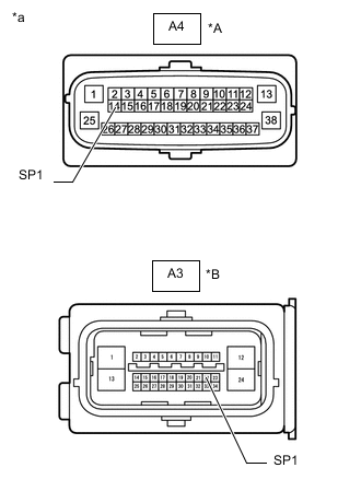
*A w/ VSC *B w/o VSC *a Front view of wire harness connector
(to Brake Actuator Assembly [Skid Control ECU])
Disconnect the brake actuator assembly (skid control ECU) connector.
-
Measure the voltage according to the value(s) in the table below.
Standard Voltage w/ VSC Tester Connection Switch Condition Specified Condition A4-14 (SP1) - Body ground Ignition switch ON 11 to 14 V w/o VSC Tester Connection Switch Condition Specified Condition A3-22 (SP1) - Body ground Ignition switch ON 11 to 14 V Result Proceed to OK NG
NG
CHECK HARNESS AND CONNECTOR (COMBINATION METER ASSEMBLY - BRAKE ACTUATOR ASSEMBLY [SKID CONTROL ECU]) Click here
OK
-
-
CHECK COMBINATION METER ASSEMBLY (INPUT WAVEFORM)
-
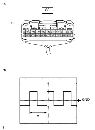
*a Component with harness connected
(Combination Meter Assembly)
*b Waveform Remove the combination meter assembly with the connector(s) still connected.
-
Connect an oscilloscope to terminal G9-18 (SI) and body ground.
-
Check the signal waveform according to the condition(s) in the table below.
Measurement Condition Item Condition Tester Connection G9-18 (SI) - Body ground Tool Setting 5 V/DIV, 20 ms./DIV Vehicle Condition Driving at approximately 20 km/h (12 mph) Tech Tips
When the system is functioning normally, one wheel revolution generates 4 pulses. As the vehicle speed increases, the width indicated by A in the illustration narrows.
OK The waveform displayed is as shown in the illustration. Result Proceed to OK NG
OK 
REPLACE COMBINATION METER ASSEMBLY Click here
NG
REPLACE BRAKE ACTUATOR ASSEMBLY (SKID CONTROL ECU) w/ VSC: Click here
REPLACE BRAKE ACTUATOR ASSEMBLY (SKID CONTROL ECU) w/o VSC: Click here -
-
CHECK HARNESS AND CONNECTOR (COMBINATION METER ASSEMBLY - CERTIFICATION ECU [SMART KEY ECU ASSEMBLY])
-
*1: for 1GR-FE
-
*2: for 1TR-FE, 2TR-FE
-
*3: for 1GD-FTV, 2GD-FTV
-
*4: for 1KD-FTV, 2KD-FTV
-
*5: w/ Body ECU
-
*6: for 1KD-FTV, Automatic Transmission
-
*7: w/ Navigation System
-
*8: w/ Audio and Visual System (for Radio and Display Type)
-
*9: w/ Audio and Visual System (for Radio Receiver Type)
-
*10: for 5L-E
-
*11: w/ Telematics System
-
Disconnect the G9 combination meter assembly connector.
-
Disconnect the G88*1, G45*2, G85*3, G83*4 or G120*10 ECM connector.
-
Disconnect the G69 certification ECU (smart key ECU assembly) connector.
-
Disconnect the G27 body ECU connector.*5
-
Disconnect the G90 TCM connector.*6
-
Disconnect the G113 navigation receiver assembly connector.*7
-
Disconnect the G37 radio and display receiver assembly connector.*8
-
Disconnect the G117 radio receiver assembly connector.*9
-
Disconnect the G130 telematics transceiver connector.*11
-
Measure the resistance according to the value(s) in the table below.
Standard Resistance Tester Connection Condition Specified Condition G9-19 (+S) - G69-7 (SPD) Always Below 1 Ω G9-19 (+S) or G69-7 (SPD) - Body ground Always 10 kΩ or higher Result Proceed to OK NG
OK
REPLACE CERTIFICATION ECU (SMART KEY ECU ASSEMBLY)
NG
REPAIR OR REPLACE HARNESS OR CONNECTOR
-
-
CHECK HARNESS AND CONNECTOR (COMBINATION METER ASSEMBLY - BODY ECU)
-
*1: for 1GR-FE
-
*2: for 1TR-FE, 2TR-FE
-
*3: for 1GD-FTV, 2GD-FTV
-
*4: for 1KD-FTV, 2KD-FTV
-
*5: w/ Entry and Start System
-
*6: for 1KD-FTV, Automatic Transmission
-
*7: w/ Navigation System
-
*8: w/ Audio and Visual System (for Radio and Display Type)
-
*9: w/ Audio and Visual System (for Radio Receiver Type)
-
*10: for 5L-E
-
*11: w/ Telematics System
-
Disconnect the G9 combination meter assembly connector.
-
Disconnect the G88*1, G45*2, G85*3, G83*4 or G120*10 ECM connector.
-
Disconnect the G69 certification ECU (smart key ECU assembly) connector.*5
-
Disconnect the G27 body ECU connector.
-
Disconnect the G90 TCM connector.*6
-
Disconnect the G113 navigation receiver assembly connector.*7
-
Disconnect the G37 radio and display receiver assembly connector.*8
-
Disconnect the G117 radio receiver assembly connector.*9
-
Disconnect the G130 telematics transceiver connector.*11
-
Measure the resistance according to the value(s) in the table below.
Standard Resistance Tester Connection Condition Specified Condition G9-19 (+S) - G27-5 (SPD) Always Below 1 Ω G9-19 (+S) or G27-5 (SPD) - Body ground Always 10 kΩ or higher Result Proceed to OK NG
OK
REPLACE BODY ECU for LHD: Click here
REPLACE BODY ECU for RHD: Click hereNG
REPAIR OR REPLACE HARNESS OR CONNECTOR
-
-
CHECK HARNESS AND CONNECTOR (COMBINATION METER ASSEMBLY - TCM)
-
*1: w/ Entry and Start System
-
*2: w/ Body ECU
-
*3: w/ Navigation System
-
*4: w/ Audio and Visual System (for Radio and Display Type)
-
*5: w/ Audio and Visual System (for Radio Receiver Type)
-
*6: w/ Telematics System
-
Disconnect the G9 combination meter assembly connector.
-
Disconnect the G83 ECM connector.
-
Disconnect the G69 certification ECU (smart key ECU assembly) connector.*1
-
Disconnect the G27 body ECU connector.*2
-
Disconnect the G90 TCM connector.
-
Disconnect the G113 navigation receiver assembly connector.*3
-
Disconnect the G37 radio and display receiver assembly connector.*4
-
Disconnect the G117 radio receiver assembly connector.*5
-
Disconnect the G130 telematics transceiver connector.*6
-
Measure the resistance according to the value(s) in the table below.
Standard Resistance Tester Connection Condition Specified Condition G9-19 (+S) - G90-25 (SPD1) Always Below 1 Ω G9-19 (+S) or G90-25 (SPD1) - Body ground Always 10 kΩ or higher Result Proceed to OK NG
OK
REPLACE TCM Click here
NG
REPAIR OR REPLACE HARNESS OR CONNECTOR
-
-
CHECK HARNESS AND CONNECTOR (COMBINATION METER ASSEMBLY - NAVIGATION RECEIVER ASSEMBLY)
-
*1: for 1GR-FE
-
*2: for 1TR-FE, 2TR-FE
-
*3: for 1GD-FTV, 2GD-FTV
-
*4: for 1KD-FTV, 2KD-FTV
-
*5: w/ Entry and Start System
-
*6: w/ Body ECU
-
*7: for 1KD-FTV, Automatic Transmission
-
*8: for 5L-E
-
*9: w/ Telematics System
-
Disconnect the G9 combination meter assembly connector.
-
Disconnect the G88*1, G45*2, G85*3, G83*4 or G120*8 ECM connector.
-
Disconnect the G69 certification ECU (smart key ECU assembly) connector.*5
-
Disconnect the G27 body ECU connector.*6
-
Disconnect the G90 TCM connector.*7
-
Disconnect the G113 navigation receiver assembly connector.
-
Disconnect the G130 telematics transceiver connector.*9
-
Measure the resistance according to the value(s) in the table below.
Standard Resistance Tester Connection Condition Specified Condition G9-19 (+S) - G113-17 (SPD) Always Below 1 Ω G9-19 (+S) or G113-17 (SPD) - Body ground Always 10 kΩ or higher Result Proceed to OK NG
OK
REPLACE NAVIGATION RECEIVER ASSEMBLY Click here
NG
REPAIR OR REPLACE HARNESS OR CONNECTOR
-
-
CHECK HARNESS AND CONNECTOR (COMBINATION METER ASSEMBLY - RADIO AND DISPLAY RECEIVER ASSEMBLY)
-
*1: for 1GR-FE
-
*2: for 1TR-FE, 2TR-FE
-
*3: for 1GD-FTV, 2GD-FTV
-
*4: for 1KD-FTV, 2KD-FTV
-
*5: w/ Entry and Start System
-
*6: w/ Body ECU
-
*7: for 1KD-FTV, Automatic Transmission
-
*8: for 5L-E
-
*9: w/ Telematics System
-
Disconnect the G9 combination meter assembly connector.
-
Disconnect the G88*1, G45*2, G85*3, G83*4 or G120*8 ECM connector.
-
Disconnect the G69 certification ECU (smart key ECU assembly) connector.*5
-
Disconnect the G27 body ECU connector.*6
-
Disconnect the G90 TCM connector.*7
-
Disconnect the G37 radio and display receiver assembly connector.
-
Disconnect the G130 telematics transceiver connector.*9
-
Measure the resistance according to the value(s) in the table below.
Standard Resistance Tester Connection Condition Specified Condition G9-19 (+S) - G37-17 (SPD) Always Below 1 Ω G9-19 (+S) or G37-17 (SPD) - Body ground Always 10 kΩ or higher Result Proceed to OK NG
OK
REPLACE RADIO AND DISPLAY RECEIVER ASSEMBLY Click here
NG
REPAIR OR REPLACE HARNESS OR CONNECTOR
-
-
CHECK HARNESS AND CONNECTOR (COMBINATION METER ASSEMBLY - RADIO RECEIVER ASSEMBLY)
-
*1: for 1GR-FE
-
*2: for 1TR-FE, 2TR-FE
-
*3: for 1GD-FTV, 2GD-FTV
-
*4: for 1KD-FTV, 2KD-FTV
-
*5: w/ Entry and Start System
-
*6: w/ Body ECU
-
*7: for 1KD-FTV, Automatic Transmission
-
*8: for 5L-E
-
*9: w/ Telematics System
-
Disconnect the G9 combination meter assembly connector.
-
Disconnect the G88*1, G45*2, G85*3, G83*4 or G120*8 ECM connector.
-
Disconnect the G69 certification ECU (smart key ECU assembly) connector.*5
-
Disconnect the G27 body ECU connector.*6
-
Disconnect the G90 TCM connector.*7
-
Disconnect the G117 radio receiver assembly connector.
-
Disconnect the G130 telematics transceiver connector.*9
-
Measure the resistance according to the value(s) in the table below.
Standard Resistance Tester Connection Condition Specified Condition G9-19 (+S) - G117-17 (SPD) Always Below 1 Ω G9-19 (+S) or G117-17 (SPD) - Body ground Always 10 kΩ or higher Result Proceed to OK NG
OK
REPLACE RADIO RECEIVER ASSEMBLY Click here
NG
REPAIR OR REPLACE HARNESS OR CONNECTOR
-
-
CHECK HARNESS AND CONNECTOR (COMBINATION METER ASSEMBLY - ECM)
-
*1: for 1GR-FE
-
*2: for 1TR-FE, 2TR-FE
-
*3: for 1GD-FTV, 2GD-FTV
-
*4: for 1KD-FTV, 2KD-FTV
-
*5: w/ Entry and Start System
-
*6: w/ Body ECU
-
*7: for 1KD-FTV, Automatic Transmission
-
*8: w/ Navigation System
-
*9: w/ Audio and Visual System (for Radio and Display Type)
-
*10: w/ Audio and Visual System (for Radio Receiver Type)
-
*11: for 5L-E
-
*12: w/ Telematics System
-
Disconnect the G9 combination meter assembly connector.
-
Disconnect the G88*1, G45*2, G85*3, G83*4 or G120*11 ECM connector.
-
Disconnect the G69 certification ECU (smart key ECU assembly) connector.*5
-
Disconnect the G27 body ECU connector.*6
-
Disconnect the G90 TCM connector.*7
-
Disconnect the G113 navigation receiver assembly connector.*8
-
Disconnect the G37 radio and display receiver assembly connector.*9
-
Disconnect the G117 radio receiver assembly connector.*10
-
Disconnect the G130 telematics transceiver connector.*12
-
Measure the resistance according to the value(s) in the table below.
Standard Resistance for 1GR-FE Tester Connection Condition Specified Condition G9-19 (+S) - G88-12 (SPD) Always Below 1 Ω G9-19 (+S) or G88-12 (SPD) - Body ground Always 10 kΩ or higher for 1TR-FE, 2TR-FE Tester Connection Condition Specified Condition G9-19 (+S) - G45-23 (SPD) Always Below 1 Ω G9-19 (+S) or G45-23 (SPD) - Body ground Always 10 kΩ or higher for 1GD-FTV, 2GD-FTV Tester Connection Condition Specified Condition G9-19 (+S) - G85-10 (SPD) Always Below 1 Ω G9-19 (+S) or G85-10 (SPD) - Body ground Always 10 kΩ or higher for 1KD-FTV, 2KD-FTV Tester Connection Condition Specified Condition G9-19 (+S) - G83-17 (SPD) Always Below 1 Ω G9-19 (+S) or G83-17 (SPD) - Body ground Always 10 kΩ or higher for 5L-E Tester Connection Condition Specified Condition G9-19 (+S) - G120-25 (SP1) Always Below 1 Ω G9-19 (+S) or G120-25 (SP1) - Body ground Always 10 kΩ or higher Result Proceed to OK NG
OK
REPLACE ECM for 1GR-FE: Click here
REPLACE ECM for 1TR-FE: Click here
REPLACE ECM for 2TR-FE: Click here
REPLACE ECM for 1GD-FTV: Click here
REPLACE ECM for 2GD-FTV: Click here
REPLACE ECM for 1KD-FTV: Click here
REPLACE ECM for 2KD-FTV: Click here
REPLACE ECM for 5L-E: Click hereNG
REPAIR OR REPLACE HARNESS OR CONNECTOR
-
-
CHECK HARNESS AND CONNECTOR (COMBINATION METER ASSEMBLY - TELEMATICS TRANSCEIVER)
-
*1: for 2TR-FE
-
*2: for 1GD-FTV, 2GD-FTV
-
*3: w/ Entry and Start System
-
*4: w/ Body ECU
-
*5: w/ Audio and Visual System (for Radio and Display Type)
-
*6: w/ Audio and Visual System (for Radio Receiver Type)
-
Disconnect the G9 combination meter assembly connector.
-
Disconnect the G45*1 or G85*2 ECM connector.
-
Disconnect the G69 certification ECU (smart key ECU assembly) connector.*3
-
Disconnect the G27 body ECU connector.*4
-
Disconnect the G37 radio and display receiver assembly connector.*5
-
Disconnect the G117 radio receiver assembly connector.*6
-
Disconnect the G130 telematics transceiver connector.
-
Measure the resistance according to the value(s) in the table below.
Standard Resistance Tester Connection Condition Specified Condition G9-19 (+S) - G130-10 (SPDP) Always Below 1 Ω G9-19 (+S) or G130-10 (SPDP) - Body ground Always 10 kΩ or higher Result Proceed to OK NG
OK
REPLACE TELEMATICS TRANSCEIVER Click here
NG
REPAIR OR REPLACE HARNESS OR CONNECTOR
-
-
CHECK COMBINATION METER ASSEMBLY (INPUT WAVEFORM)
-
*a Component with harness connected
(Combination Meter Assembly)
*b Waveform Remove the combination meter assembly with the connector(s) still connected.
-
Connect an oscilloscope to terminal G9-18 (SI) and body ground.
-
Check the signal waveform according to the condition(s) in the table below.
Measurement Condition Item Condition Tester Connection G9-18 (SI) - Body ground Tool Setting 5 V/DIV, 20 ms./DIV Vehicle Condition Driving at approximately 20 km/h (12 mph) Tech Tips
When the system is functioning normally, one wheel revolution generates 4 pulses. As the vehicle speed increases, the width indicated by A in the illustration narrows.
OK The waveform displayed is as shown in the illustration. Result Proceed to OK NG
OK
REPLACE COMBINATION METER ASSEMBLY Click here
NG
CHECK HARNESS AND CONNECTOR (SPEEDOMETER SENSOR - COMBINATION METER ASSEMBLY AND BODY GROUND) Click here
-
-
CHECK HARNESS AND CONNECTOR (COMBINATION METER ASSEMBLY - BRAKE ACTUATOR ASSEMBLY [SKID CONTROL ECU])
-
Disconnect the G9 combination meter assembly connector.
-
Disconnect the A4*1 or A3*2 brake actuator assembly (skid control ECU) connector.
-
*1: w/ VSC
-
*2: w/o VSC
-
-
Measure the resistance according to the value(s) in the table below.
Standard Resistance w/ VSC Tester Connection Condition Specified Condition G9-18 (SI) - A4-14 (SP1) Always Below 1 Ω G9-18 (SI) or A4-14 (SP1) - Body ground Always 10 kΩ or higher w/o VSC Tester Connection Condition Specified Condition G9-18 (SI) - A3-22 (SP1) Always Below 1 Ω G9-18 (SI) or A3-22 (SP1) - Body ground Always 10 kΩ or higher Result Proceed to OK NG
OK
REPLACE COMBINATION METER ASSEMBLY Click here
NG
REPAIR OR REPLACE HARNESS OR CONNECTOR
-
-
CHECK HARNESS AND CONNECTOR (SPEEDOMETER SENSOR - COMBINATION METER ASSEMBLY AND BODY GROUND)
-
Disconnect the C62 speedometer sensor connector.
-
Disconnect the G9 and G10 combination meter assembly connectors.
-
Measure the resistance according to the value (s) in the table below.
Standard Resistance Tester Connection Condition Specified Condition C62-3 (SI) - G9-18 (SI) Always Below 1 Ω C62-3 (SI) or G9-18 (SI) - Body ground Always 10 kΩ or higher Result Proceed to OK NG
OK
REPLACE SPEEDOMETER SENSOR Click here
NG
REPAIR OR REPLACE HARNESS OR CONNECTOR
-