METER / GAUGE SYSTEM, Diagnostic DTC:B1507, B1508
| DTC Code | DTC Name |
|---|---|
| B1507 | Open in Turn Signal Circuit |
| B1508 | Short in Turn Signal / Hazard Flasher Circuit |
DESCRIPTION
| DTC No. | Detection Item | DTC Detection Condition | Trouble Area |
|---|---|---|---|
| B1507 | Open in Turn Signal Circuit | Open in turn signal light circuit. |
|
| B1508 | Short in Turn Signal / Hazard Flasher Circuit | Short in turn signal light circuit or hazard warning light circuit. |
|
-
*1: w/ Outer Rear View Mirror Type Side Turn Signal Light
-
*2: w/ Deck
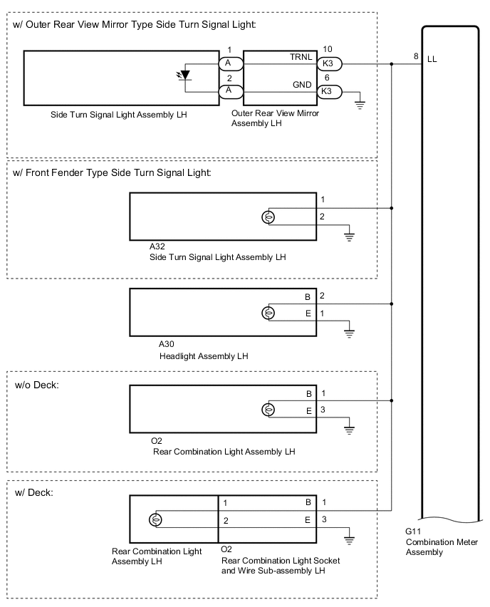
WIRING DIAGRAM
CAUTION / NOTICE / HINT
Note
-
When replacing the combination meter assembly, make sure to replace it with a new one.
-
Inspect the bulbs for circuits related to this system before performing the following procedure.
PROCEDURE
-
CHECK FOR DTC
-
Clear the DTCs.
Body Electrical > Combination Meter > Clear DTCs -
Recheck for DTCs and check that no DTCs are output.
Body Electrical > Combination Meter > Trouble CodesOK B1507 and B1508 are not output. Result Proceed to OK NG
OK 
USE SIMULATION METHOD TO CHECK Click here
NG 
-
-
CHECK TURN SIGNAL LIGHT
-
Check the illumination of each turn signal light.
Result Result Proceed to LH side turn signal light does not illuminate. A RH side turn signal light does not illuminate. B
B 
CHECK HARNESS AND CONNECTOR (RH SIDE CIRCUIT) Click here
A
-
-
CHECK HARNESS AND CONNECTOR (LH SIDE CIRCUIT)
-
*1: w/ Outer Rear View Mirror Type Side Turn Signal Light
-
*2: w/ Front Fender Type Side Turn Signal Light
-
*3: w/o Deck
-
*4: w/ Deck
-
Disconnect the G11 combination meter assembly connector.
-
Disconnect the A30 headlight assembly LH connector.
-
Disconnect the K3 outer rear view mirror assembly LH connector.*1
-
Disconnect the A32 side turn signal light assembly LH connector.*2
-
Disconnect the O2 rear combination light assembly LH*3 or rear combination light socket and wire sub-assembly LH*4 connector.
-
Measure the resistance according to the value(s) in the table below.
Standard Resistance Tester Connection Condition Specified Condition G11-8 (LL) - A30-2 (B) Always Below 1 Ω G11-8 (LL) - K3-10 (TRNL)*1 Always Below 1 Ω G11-8 (LL) - A32-1*2 Always Below 1 Ω G11-8 (LL) - O2-1 (B) Always Below 1 Ω A30-1 (E) - Body ground Always Below 1 Ω K3-6 (GND) - Body ground*1 Always Below 1 Ω A32-2 - Body ground*2 Always Below 1 Ω O2-3 (E) - Body ground Always Below 1 Ω G11-8 (LL) - Body ground Always 10 kΩ or higher Result Result Proceed to OK (w/ Outer Rear View Mirror Type Side Turn Signal Light) A OK (w/ Front Fender Type Side Turn Signal Light) B NG C
B
GO TO STEP 5 Click here
C
REPAIR OR REPLACE HARNESS OR CONNECTOR
A
-
-
INSPECT OUTER REAR VIEW MIRROR ASSEMBLY LH
-
Remove the outer rear view mirror assembly LH.
-
Inspect the outer rear view mirror assembly LH.
Result Proceed to OK NG
NG
INSPECT SIDE TURN SIGNAL LIGHT ASSEMBLY LH Click here
OK
-
-
CHECK REAR COMBINATION LIGHT TYPE
-
Check the rear combination light type.
Result Result Proceed to w/ Deck A w/o Deck B
B
REPLACE COMBINATION METER ASSEMBLY Click here
A
-
-
INSPECT REAR COMBINATION LIGHT SOCKET AND WIRE SUB-ASSEMBLY LH
-
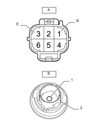
Remove the rear combination light socket and wire sub-assembly LH.
-
Measure the resistance according to the value(s) in the table below.
Standard Resistance Tester Connection Condition Specified Condition A-1 (B) - B-1 Always Below 1 Ω A-3 (E) - B-2 Always Below 1 Ω A-1 (B) or B-1 - Body ground Always 10 kΩ or higher A-3 (E) or B-2 - Body ground Always 10 kΩ or higher Result Proceed to OK NG
OK
REPLACE COMBINATION METER ASSEMBLY Click here
NG
REPLACE REAR COMBINATION LIGHT SOCKET AND WIRE SUB-ASSEMBLY LH Click here
-
-
INSPECT SIDE TURN SIGNAL LIGHT ASSEMBLY LH
-
Remove the side turn signal light assembly LH.
-
Inspect the side turn signal light assembly LH.
Result Proceed to OK NG
OK
REPLACE OUTER REAR VIEW MIRROR ASSEMBLY LH Click here
NG
REPLACE SIDE TURN SIGNAL LIGHT ASSEMBLY LH Click here
-
-
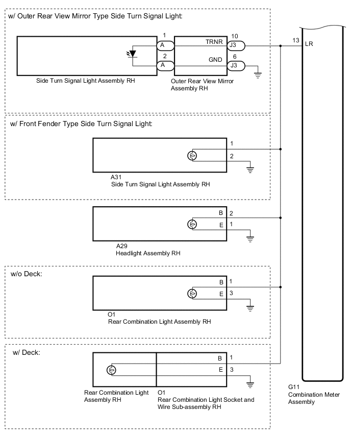
CHECK HARNESS AND CONNECTOR (RH SIDE CIRCUIT)
-
*1: w/ Outer Rear View Mirror Type Side Turn Signal Light
-
*2: w/ Front Fender Type Side Turn Signal Light
-
*3: w/o Deck
-
*4: w/ Deck
-
Disconnect the G11 combination meter assembly connector.
-
Disconnect the A29 headlight assembly RH connector.
-
Disconnect the J3 outer rear view mirror assembly RH connector.*1
-
Disconnect the A31 side turn signal light assembly RH connector.*2
-
Disconnect the O1 rear combination light assembly RH*3 or rear combination light socket and wire sub-assembly RH*4 connector.
-
Measure the resistance according to the value(s) in the table below.
Standard Resistance Tester Connection Condition Specified Condition G11-13 (LR) - A29-2 (B) Always Below 1 Ω G11-13 (LR) - J3-10 (TRNR)*1 Always Below 1 Ω G11-13 (LR) - A31-1*2 Always Below 1 Ω G11-13 (LR) - O1-1 (B) Always Below 1 Ω A29-1 (E) - Body ground Always Below 1 Ω J3-6 (GND) - Body ground*1 Always Below 1 Ω A31-2 - Body ground*2 Always Below 1 Ω O1-3 (E) - Body ground Always Below 1 Ω G11-13 (LR) - Body ground Always 10 kΩ or higher Result Result Proceed to OK (w/ Outer Rear View Mirror Type Side Turn Signal Light) A OK (w/ Front Fender Type Side Turn Signal Light) B NG C
B
GO TO STEP 10 Click here
C
REPAIR OR REPLACE HARNESS OR CONNECTOR
A
-
-
INSPECT OUTER REAR VIEW MIRROR ASSEMBLY RH
-
Remove the outer rear view mirror assembly RH.
-
Inspect the outer rear view mirror assembly RH.
Result Proceed to OK NG
NG
INSPECT SIDE TURN SIGNAL LIGHT ASSEMBLY RH Click here
OK
-
-
CHECK REAR COMBINATION LIGHT TYPE
-
Check the rear combination light type.
Result Result Proceed to w/ Deck A w/o Deck B
B
REPLACE COMBINATION METER ASSEMBLY Click here
A
-
-
INSPECT REAR COMBINATION LIGHT SOCKET AND WIRE SUB-ASSEMBLY RH
-
Remove the rear combination light socket and wire sub-assembly RH.
-
Measure the resistance according to the value(s) in the table below.
Standard Resistance Tester Connection Condition Specified Condition A-1 (B) - B-1 Always Below 1 Ω A-3 (E) - B-2 Always Below 1 Ω A-1 (B) or B-1 - Body ground Always 10 kΩ or higher A-3 (E) or B-2 - Body ground Always 10 kΩ or higher Result Proceed to OK NG
OK
REPLACE COMBINATION METER ASSEMBLY Click here
NG
REPLACE REAR COMBINATION LIGHT SOCKET AND WIRE SUB-ASSEMBLY RH Click here
-
-
INSPECT SIDE TURN SIGNAL LIGHT ASSEMBLY RH
-
Remove the side turn signal light assembly RH.
-
Inspect the side turn signal light assembly RH.
Result Proceed to OK NG
OK
REPLACE OUTER REAR VIEW MIRROR ASSEMBLY RH Click here
NG
REPLACE SIDE TURN SIGNAL LIGHT ASSEMBLY RH Click here
-