ELECTRICAL KEY OSCILLATOR(for Instrument Panel Side) INSTALLATION
CAUTION / NOTICE / HINT
Tech Tips
-
Use the same procedure for RHD and LHD vehicles.
-
The procedure listed below is for LHD vehicles.
PROCEDURE
-
INSTALL NO. 1 INDOOR ELECTRICAL KEY ANTENNA ASSEMBLY
Note
Do not reuse dropped or damaged parts.
-
Attach the clamp to install the No. 1 indoor electrical key antenna assembly.
-
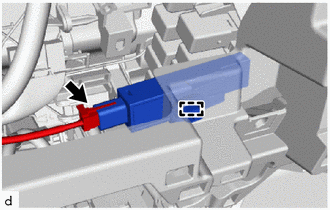
Connect the connector.
-
-
INSTALL NAVIGATION RECEIVER ASSEMBLY WITH BRACKET
-
INSTALL RADIO AND DISPLAY RECEIVER ASSEMBLY WITH BRACKET
-
INSTALL RADIO RECEIVER ASSEMBLY WITH BRACKET
-
INSTALL AIR CONDITIONING CONTROL ASSEMBLY (for Automatic Air Conditioning System)
-
CONNECT AIR MIX DAMPER CONTROL CABLE SUB-ASSEMBLY (for Manual Air Conditioning System)
-
CONNECT AIR INLET DAMPER CONTROL CABLE SUB-ASSEMBLY (for Manual Air Conditioning System)
-
CONNECT DEFROSTER DAMPER CONTROL CABLE SUB-ASSEMBLY (for Manual Air Conditioning System)
-
INSTALL INTEGRATION PANEL SUB-ASSEMBLY WITH AIR CONDITIONING CONTROL ASSEMBLY (for Manual Air Conditioning System)
-
INSTALL AIR INLET DAMPER CONTROL LEVER (for Manual Air Conditioning System)
-
INSTALL CONTROL KNOB SUB-ASSEMBLY (for Manual Air Conditioning System)
-
INSTALL INSTRUMENT CLUSTER FINISH PANEL ASSEMBLY
-
INSTALL NO. 1 INSTRUMENT PANEL BOX DOOR SUB-ASSEMBLY
-
INSTALL INSTRUMENT CLUSTER FINISH PANEL GARNISH ASSEMBLY
-
INSTALL STEERING WHEEL ASSEMBLY
-
CONNECT CABLE TO NEGATIVE BATTERY TERMINAL
Note
When disconnecting the cable, some systems need to be initialized after the cable is reconnected Click here.