THEFT DETERRENT SYSTEM Intrusion Sensor Circuit
DESCRIPTION
If no warnings operate or the system can be set even though the conditions to set the system are not met, the body ECU cannot perform recognition due to a cutoff of the ON signal from the courtesy light switch from the doors, engine hood or back door, or some other problem.
If the automatic alarm operates when it should not operate, it may be due to a false detection by the intrusion sensor (theft warning ultrasonic sensor) or due to the ON signal being input when there is a short circuit in the courtesy light switch of the doors, engine hood or back door, or some other problem which would cause this to happen.
Tech Tips
In the following situations, the intrusion sensor (theft warning ultrasonic sensor) may operate and cause the automatic alarm system to operate even when the sensor is normal.
-
The driver steps away from the vehicle while other people, pets, etc. are in the vehicle.
-
There are things which move easily inside the vehicle, such as things hanging inside the vehicle or clothing hanging from the coat hooks.
-
A window or the sliding roof is open.
-
The vehicle is parked in a place with a lot of vibration or noise such as a parking garage.
-
The vehicle is being washed using a high-pressure spray gun or an automatic car washing machine.
-
The vehicle is continuously being struck or is vibrating due to hail or lightning.
-
The vehicle is continuously being subjected to impacts or is vibrating when snow or ice is being removed from the vehicle.
-
A frost prevention sheet which has an aluminum film is moved by wind, etc.
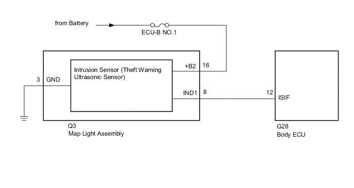
WIRING DIAGRAM
CAUTION / NOTICE / HINT
Note
-
Inspect the fuses for circuits related to this system before performing the following procedure.
-
w/ Door control Battery:
As the door control battery is installed between the vehicle battery and body ECU, first perform the inspections to confirm that there are no malfunctions in the power source circuit for the body ECU before performing this troubleshooting procedure.
-
w/ Automatic Light Control System:
If the body ECU has been replaced, it is necessary to initialize the body ECU.
PROCEDURE
-
CHECK HARNESS AND CONNECTOR (MAP LIGHT ASSEMBLY - BATTERY AND BODY GROUND)
-
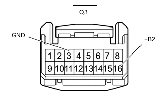
*a Front view of wire harness connector
(to Map Light Assembly)
Disconnect the map light assembly connector.
-
Measure the voltage according to the value(s) in the table below.
Standard Voltage Tester Connection Condition Specified Condition Q3-16 (+B2) - Body ground Always 11 to 14 V -
Measure the resistance according to the value(s) in the table below.
Standard Resistance Tester Connection Condition Specified Condition Q3-3 (GND) - Body ground Always Below 1 Ω Result Proceed to OK NG
NG 
REPAIR OR REPLACE HARNESS OR CONNECTOR
OK 
-
-
CHECK WAVEFORM (INTRUSION SENSOR [THEFT WARNING ULTRASONIC SENSOR]) (IND1)
-
Using an oscilloscope, check the waveform.
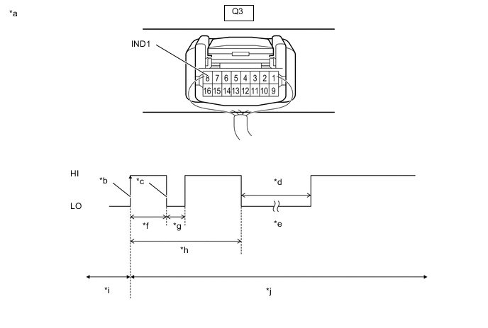
*a Component with harness connected
(Map Light Assembly)
*b IND1 Initial Signal *c IND1 Initial Response *d Approximately 1.0 seconds *e Initial Diagnosis *f Approximately 1.0 to 1.6 seconds *g Approximately 0.05 seconds *h Approximately 5.5 seconds *i Disarmed State *j Arming Preparation State Measurement Condition Item Content Tester Connection Q3-8 (IND1) - Body ground Tool Setting 2 V/DIV., 100 ms./DIV. Condition Theft deterrent system is set (system changes from disarmed state to arming preparation state) Tech Tips
-
If the intrusion sensor (theft warning ultrasonic sensor) is normal, an initial response is output in response to the HI input from the body ECU.
-
If the waveform output remains LO, there may be a problem with the body ECU, as there is no input from the body ECU.
OK The waveform displays properly (HI is 6.5 V or higher and LO is below 1 V). Result Result Proceed to OK (There is an initial response) A NG (Waveform output remains LO) B NG (There is no initial response and the waveform output remains HI) C -
A
PROCEED TO NEXT SUSPECTED AREA SHOWN IN PROBLEM SYMPTOMS TABLE Click here
C 
INSPECT MAP LIGHT ASSEMBLY Click here
B
-
-
CHECK HARNESS AND CONNECTOR (BODY ECU - MAP LIGHT ASSEMBLY)
-
Disconnect the G28 body ECU connector.
-
Disconnect the Q3 map light assembly connector.
-
Measure the resistance according to the value(s) in the table below.
Standard Resistance Tester Connection Condition Specified Condition G28-12 (ISIF) - Q3- 8 (IND1) Always Below 1 Ω G28-12 (ISIF) - Body ground Always 10 kΩ or higher Q3- 8 (IND1) - Body ground Always 10 kΩ or higher Result Proceed to OK (for LHD) OK (for RHD) NG
OK (for LHD)
REPLACE BODY ECU Click here
OK (for RHD)
REPLACE BODY ECU Click here
NG
REPAIR OR REPLACE HARNESS OR CONNECTOR
-
-
INSPECT MAP LIGHT ASSEMBLY
-
Remove the map light assembly.
-
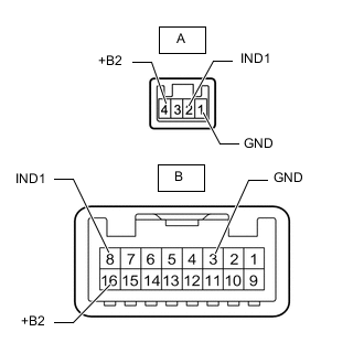
Measure the resistance according to the value(s) in the table below.
Standard Resistance Tester Connection Condition Specified Condition A-1 (GND) -B-3 (GND) Always Below 1 Ω A-2 (IND1) -B-8 (IND1) Always Below 1 Ω A-4 (+B2) - B-16 (+B2) Always Below 1 Ω Result Proceed to OK NG
OK
REPLACE INTRUSION SENSOR (THEFT WARNING ULTRASONIC SENSOR) Click here
NG
REPLACE MAP LIGHT ASSEMBLY Click here
-