THEFT DETERRENT SYSTEM Security Horn Circuit
DESCRIPTION
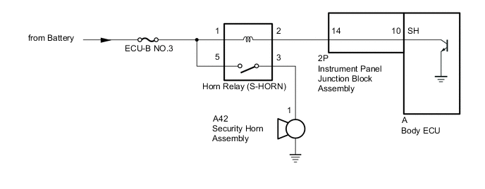
When the theft deterrent system is switched from the armed state to the alarm sounding state, the body ECU transmits a signal to cause the security horn to sound at intervals of 0.4 seconds.
WIRING DIAGRAM
CAUTION / NOTICE / HINT
Note
-
Inspect the fuses for circuits related to this system before performing the following procedure.
-
w/ Door Control Battery:
As the door control battery is installed between the vehicle battery and body ECU, first perform the inspections to confirm that there are no malfunctions in the power source circuit for the body ECU before performing this troubleshooting procedure.
-
w/ Automatic Light Control System:
If the body ECU has been replaced, it is necessary to initialize the body ECU.
PROCEDURE
-
INSPECT SECURITY HORN ASSEMBLY
-
Remove the security horn assembly.
-
Inspect the security horn assembly.
Result Proceed to OK NG
NG 
REPLACE SECURITY HORN ASSEMBLY Click here
OK 
-
-
INSPECT HORN RELAY (S-HORN)
-
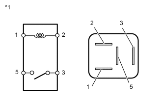
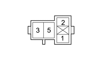
*1 Horn Relay (S-HORN) Remove the horn relay (S-HORN).
-
Measure the resistance according to the value(s) in the table below.
Standard Resistance Tester Connection Condition Specified Condition 3 - 5 Battery voltage is not applied between terminals 1 and 2 10 kΩ or higher 3 - 5 Battery voltage is applied between terminals 1 and 2 Below 1 Ω Result Proceed to OK NG
NG
REPLACE HORN RELAY (S-HORN)
OK
-
-
INSPECT INSTRUMENT PANEL JUNCTION BLOCK ASSEMBLY
-
Remove the body ECU.
-
for LHD:
-
for RHD:
-
-
Disconnect the instrument panel junction block assembly connector.
-
Measure the resistance according to the value(s) in the table below.
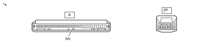
*a Component without harness connected
(Instrument Panel Junction Block Assembly)
- - Standard Resistance Tester Connection Condition Specified Condition 2P-14 - A-10 (SH) Always Below 1 Ω Result Proceed to OK NG (for LHD) NG (for RHD)
NG (for LHD)
REPLACE INSTRUMENT PANEL JUNCTION BLOCK ASSEMBLY Click here
NG (for RHD)
REPLACE INSTRUMENT PANEL JUNCTION BLOCK ASSEMBLY Click here
OK
-
-
CHECK HARNESS AND CONNECTOR (BATTERY - HORN RELAY (S-HORN))
-
Remove the horn relay (S-HORN).
-
Measure the voltage according to the value(s) in the table below.
Standard Voltage Tester Connection Condition Specified Condition Relay terminal 1 - Body ground Always 11 to 14 V Relay terminal 5 - Body ground Always 11 to 14 V Result Proceed to OK NG
NG
REPAIR OR REPLACE HARNESS OR CONNECTOR
OK
-
-
CHECK HARNESS AND CONNECTOR (HORN RELAY (S-HORN) - SECURITY HORN ASSEMBLY AND INSTRUMENT PANEL JUNCTION BLOCK ASSEMBLY)
-
Remove the horn relay (S-HORN).
-
Disconnect the A42 security horn assembly connector.
-
Disconnect the 2P instrument panel junction block assembly connector.
-
Measure the resistance according to the value(s) in the table below.
Standard Resistance Tester Connection Condition Specified Condition Relay terminal 3 - A42-1 Always Below 1 Ω Relay terminal 2 - 2P-14 Always Below 1 Ω Relay terminal 3 - Body ground Always 10 kΩ or higher Relay terminal 2 - Body ground Always 10 kΩ or higher A42-1 - Body ground Always 10 kΩ or higher 2P-14 - Body ground Always 10 kΩ or higher Result Proceed to OK (for LHD) OK (for RHD) NG
OK (for LHD)
REPLACE BODY ECU Click here
OK (for RHD)
REPLACE BODY ECU Click here
NG
REPAIR OR REPLACE HARNESS OR CONNECTOR
-