IMMOBILISER SYSTEM(w/o Entry and Start System) Engine does not Start but Initial Combustion Occurs
DESCRIPTION
If the key ID codes of the key and transponder key ECU assembly match, the immobiliser system is unset and the engine start permission signal is sent to the ECM. When the ID codes of the transponder key ECU assembly and ECM match, the engine starts.
WIRING DIAGRAM
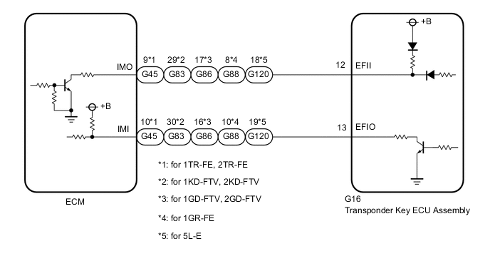
CAUTION / NOTICE / HINT
Note
If the transponder key ECU assembly or ECM is replaced, refer to Service Bulletin.
PROCEDURE
-
CLEAR DTC
-
Clear the DTCs.
Body Electrical > Immobiliser > Clear DTCs
Powertrain > Engine > Clear DTCsResult Proceed to NEXT
NEXT 
-
-
CHECK FOR DTC
-
Check for DTCs.
Body Electrical > Immobiliser > Trouble Codes
Powertrain > Engine > Trouble CodesOK DTC is not output. Result Result Proceed to DTCs are not output (for SFI System) A DTCs are not output (for ECD System) B DTCs are output C
B 
GO TO STEP 4 Click here
C 
GO TO DIAGNOSTIC TROUBLE CODE CHART Click here
A
-
-
READ VALUE USING GTS (IMMOBILISER FUEL CUT)
-
Connect the GTS to the DLC3.
-
Turn the ignition switch to ON.
-
Turn the GTS on.
-
Enter the following menus: Powertrain / Engine / Data List.
-
Read the Data List according to the display on the GTS.
Powertrain > Engine > Data ListTester Display Measurement Item Range Normal Condition Diagnostic Note Immobiliser Fuel Cut Status of immobiliser system fuel cut ON or OFF - -
Powertrain > Engine > Data ListTester Display Immobiliser Fuel Cut OK OFF is displayed after the engine is started. Result Proceed to OK (1TR-FE) OK (2TR-FE) OK (1GR-FE) NG
OK (1TR-FE)
GO TO SFI SYSTEM Click here
OK (2TR-FE)
GO TO SFI SYSTEM Click here
OK (1GR-FE)
GO TO SFI SYSTEM Click here
NG
-
-
CHECK WHETHER ENGINE STARTS
-
Using a registered key, turn the ignition switch to ON.
-
Check that the engine starts 5 seconds after the ignition switch was turned to ON.
OK Engine starts normally. Result Proceed to OK NG
OK
USE SIMULATION METHOD TO CHECK Click here
NG
-
-
CHECK ECM (TERMINAL IMI)
-
Using an oscilloscope, check the waveform. (for Gasoline)
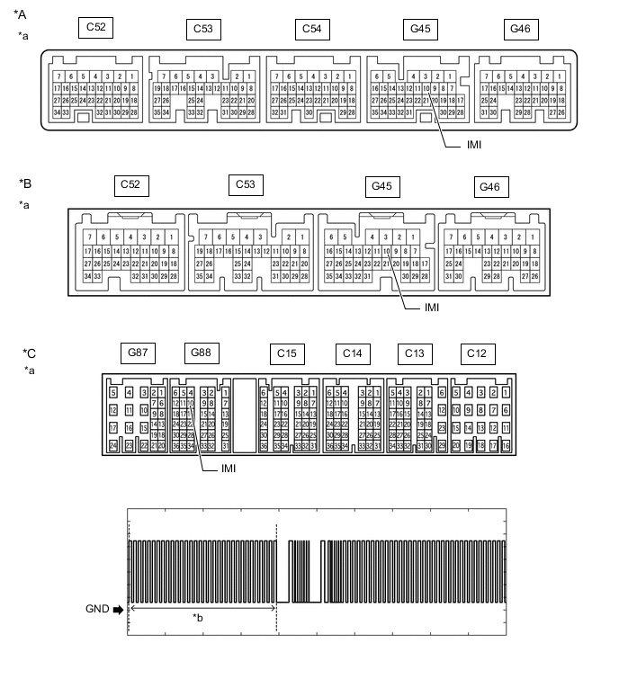
*A for 2TR-FE (for Automatic Transmission) *B for 1TR-FE, 2TR-FE (for Manual Transmission) *C for 1GR-FE - - *a Component with harness connected
(ECM)
*b Waveform A Measurement Condition Item Content Tester Connection G45-10 (IMI) - Body ground*1
G88-10 (IMI) - Body ground*2
Tool Setting 2 V/DIV., 500 ms./DIV. Condition Within 3 seconds of starter operation and initial combustion, or within 3 seconds of ignition switch first being turned to ON after cable disconnected and reconnected to negative (-) battery terminal
-
*1: for 1TR-FE, 2TR-FE
-
*2: for 1GR-FE
OK Waveform is output normally (refer to illustration) -
-
Using an oscilloscope, check the waveform. (for Diesel)
*A for 1KD-FTV, 2KD-FTV *B for 5L-E *C for 1GD-FTV, 2GD-FTV - - *a Component with harness connected
(ECM)
*b Waveform A Measurement Condition Item Content Tester Connection G83-30 (IMI) - Body ground*1
G86-16 (IMI) - Body ground*2
G120-19 (IMI) - Body ground*3
Tool Setting 2 V/DIV., 500 ms./DIV. Condition Within 3 seconds of starter operation and initial combustion, or within 3 seconds of ignition switch first being turned to ON after cable disconnected and reconnected to negative (-) battery terminal
-
*1: for 1KD-FTV, 2KD-FTV
-
*2: for 1GD-FTV, 2GD-FTV
-
*3: for 5L-E
OK Waveform is output normally (refer to illustration) Result Result Proceed to Normal waveform A Waveform A not output, or has abnormal wavelength or shape B -
B
CHECK HARNESS AND CONNECTOR (TRANSPONDER KEY ECU ASSEMBLY - ECM) Click here
A
-
-
CHECK ECM (TERMINAL IMO)
-
Using an oscilloscope, check the waveform. (for Gasoline)
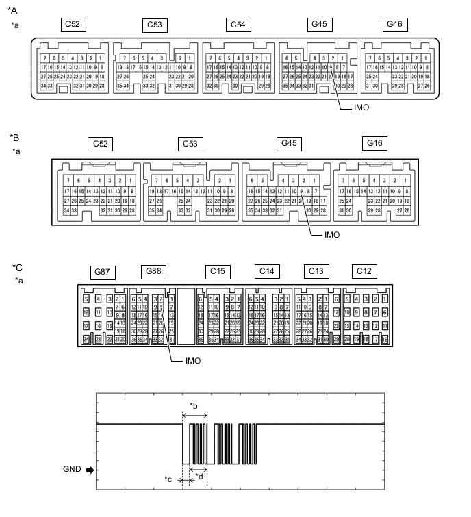
*A for 2TR-FE (for Automatic Transmission) *B for 1TR-FE, 2TR-FE (for Manual Transmission) *C for 1GR-FE - - *a Component with harness connected
(ECM)
*b Waveform B *c Approximately 160 ms *d Approximately 270 ms Measurement Condition Item Content Tester Connection G45-9 (IMO) - Body ground*1
G88-8 (IMO) - Body ground*2
Tool Setting 2 V/DIV., 500 ms./DIV. Condition Within 3 seconds of starter operation and initial combustion, or within 3 seconds of ignition switch first being turned to ON after cable disconnected and reconnected to negative (-) battery terminal
-
*1: for 1TR-FE, 2TR-FE
-
*2: for 1GR-FE
OK Waveform is output normally (refer to illustration) -
-
Using an oscilloscope, check the waveform. (for Diesel)
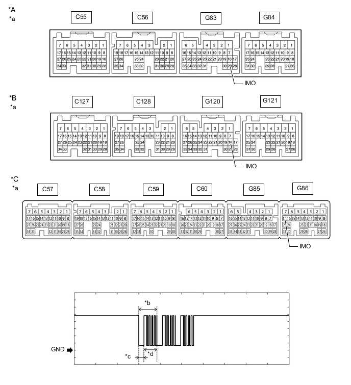
*A for 1KD-FTV, 2KD-FTV *B for 5L-E *C for 1GD-FTV, 2GD-FTV - - *a Component with harness connected
(ECM)
*b Waveform B *c Approximately 160 ms *d Approximately 270 ms Measurement Condition Item Content Tester Connection G83-29 (IMO) - Body ground*1
G86-17 (IMO) - Body ground*2
G120-18 (IMO) - Body ground*3
Tool Setting 2 V/DIV., 500 ms./DIV. Condition Within 3 seconds of starter operation and initial combustion, or within 3 seconds of ignition switch first being turned to ON after cable disconnected and reconnected to negative (-) battery terminal
-
*1: for 1KD-FTV, 2KD-FTV
-
*2: for 1GD-FTV, 2GD-FTV
-
*3: for 5L-E
OK Waveform is output normally (refer to illustration) Result Result Proceed to Normal waveform A Waveform B not output, or has abnormal wavelength or shape (for 1TR-FE) B Waveform B not output, or has abnormal wavelength or shape (for 2TR-FE) C Waveform B not output, or has abnormal wavelength or shape (for 1KD-FTV) D Waveform B not output, or has abnormal wavelength or shape (for 2KD-FTV) E Waveform B not output, or has abnormal wavelength or shape (for 1GD-FTV) F Waveform B not output, or has abnormal wavelength or shape (for 2GD-FTV) G Waveform B not output, or has abnormal wavelength or shape (for 1GR-FE) H Waveform B not output, or has abnormal wavelength or shape (for 5L-E) I -
B
REPLACE ECM Click here
C
REPLACE ECM Click here
D
REPLACE ECM Click here
E
REPLACE ECM Click here
F
REPLACE ECM Click here
G
REPLACE ECM Click here
H
REPLACE ECM Click here
I
REPLACE ECM Click here
A
-
-
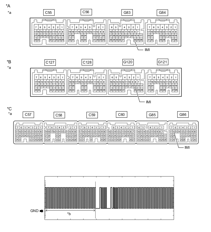
CHECK ECM (TERMINAL IMI)
-
Using an oscilloscope, check the waveform. (for Gasoline)
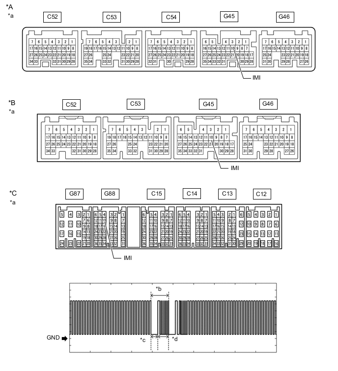
*A for 2TR-FE (for Automatic Transmission) *B for 1TR-FE, 2TR-FE (for Manual Transmission) *C for 1GR-FE - - *a Component with harness connected
(ECM)
*b Waveform C *c Approximately 160 ms *d Approximately 270 ms Measurement Condition Item Content Tester Connection G45-10 (IMI) - Body ground*1
G88-10 (IMI) - Body ground*2
Tool Setting 2 V/DIV., 500 ms./DIV. Condition Within 3 seconds of starter operation and initial combustion, or within 3 seconds of ignition switch first being turned to ON after cable disconnected and reconnected to negative (-) battery terminal
-
*1: for 1TR-FE, 2TR-FE
-
*2: for 1GR-FE
OK Waveform is output normally (refer to illustration) -
-
Using an oscilloscope, check the waveform. (for Diesel)
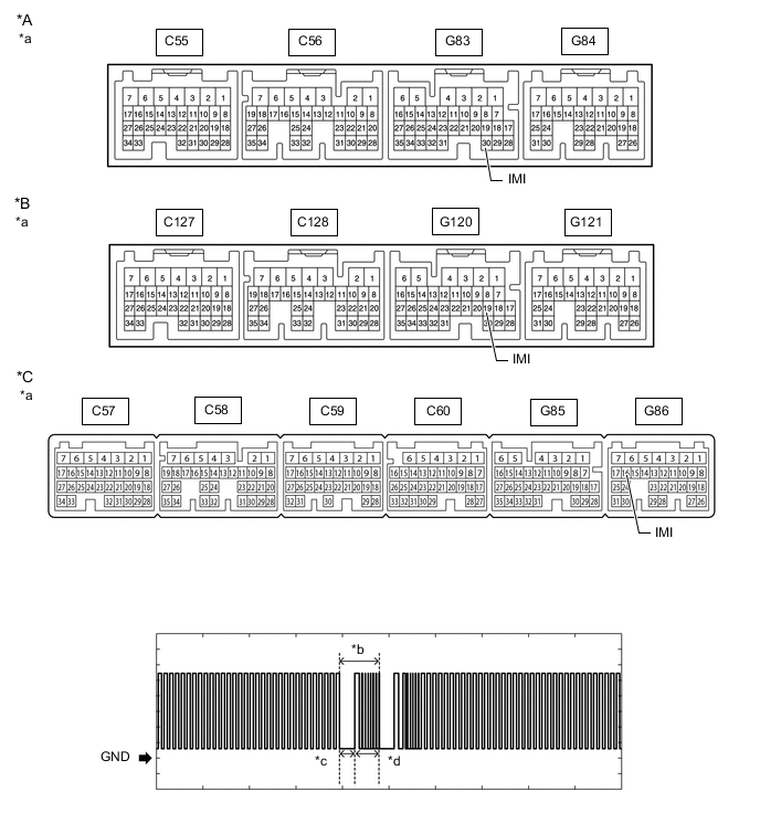
*A for 1KD-FTV, 2KD-FTV *B for 5L-E *C for 1GD-FTV, 2GD-FTV - - *a Component with harness connected
(ECM)
*b Waveform C *c Approximately 160 ms *d Approximately 270 ms Measurement Condition Item Content Tester Connection G83-30 (IMI) - Body ground*1
G86-16 (IMI) - Body ground*2
G120-19 (IMI) - Body ground*3
Tool Setting 2 V/DIV., 500 ms./DIV. Condition Within 3 seconds of starter operation and initial combustion, or within 3 seconds of ignition switch first being turned to ON after cable disconnected and reconnected to negative (-) battery terminal
-
*1: for 1KD-FTV, 2KD-FTV
-
*2: for 1GD-FTV, 2GD-FTV
-
*3: for 5L-E
OK Waveform is output normally (refer to illustration) Result Result Proceed to Normal waveform A Waveform C not output, or has abnormal wavelength or shape B -
B
GO TO STEP 10 Click here
A
-
-
REGISTER ECU COMMUNICATION ID
-
Register the communication ID between the transponder key ECU assembly and ECM.
Tech Tips
Refer to Service Bulletin.
Result Proceed to NEXT
NEXT
-
-
CHECK WHETHER ENGINE STARTS
-
Using a registered key, turn the ignition switch to ON.
-
Check that the engine starts 5 seconds after the ignition switch was turned to ON.
OK Engine starts normally. Result Proceed to OK NG
OK
END (REGISTERED COMMUNICATION ID WAS DEFECTIVE)
NG
-
-
REPLACE TRANSPONDER KEY ECU ASSEMBLY
-
Replace the transponder key ECU assembly with a new one.
Tech Tips
Refer to Service Bulletin.
Result Proceed to NEXT
NEXT
-
-
REGISTER KEY
-
Register the key.
Tech Tips
Refer to Service Bulletin.
Result Proceed to NEXT
NEXT
-
-
REGISTER ECU COMMUNICATION ID
-
Register the ECU communication ID.
Tech Tips
Refer to Service Bulletin.
Result Proceed to NEXT
NEXT
-
-
CHECK WHETHER ENGINE STARTS
-
Using a registered key, turn the ignition switch to ON.
-
Check that the engine starts 5 seconds after the ignition switch was turned to ON.
OK Engine starts normally. Result Result Proceed to OK A NG (for 1TR-FE) B NG (for 2TR-FE) C NG (for 1KD-FTV) D NG (for 2KD-FTV) E NG (for 1GD-FTV) F NG (for 1GD-FTV (w/ DPF)) G NG (for 2GD-FTV) H NG (for 2GD-FTV (w/ DPF)) I NG (for 1GR-FE) J NG (for 5L-E) K
A
END (TRANSPONDER KEY ECU ASSEMBLY WAS DEFECTIVE)
B
GO TO SFI SYSTEM Click here
C
GO TO SFI SYSTEM Click here
D
GO TO ECD SYSTEM Click here
E
GO TO ECD SYSTEM Click here
F
GO TO ECD SYSTEM Click here
G
GO TO ECD SYSTEM Click here
H
GO TO ECD SYSTEM Click here
I
GO TO ECD SYSTEM Click here
J
GO TO SFI SYSTEM Click here
K
GO TO ECD SYSTEM Click here
-
-
CHECK HARNESS AND CONNECTOR (TRANSPONDER KEY ECU ASSEMBLY - ECM)
-
Disconnect the G16 transponder key ECU assembly connector.
-
Disconnect the G45*1, G83*2, G86*3, G88*4 or G120*5 ECM connector.
-
*1: for 1TR-FE, 2TR-FE
-
*2: for 1KD-FTV, 2KD-FTV
-
*3: for 1GD-FTV, 2GD-FTV
-
*4: for 1GR-FE
-
*5: for 5L-E
-
-
Measure the resistance according to the value(s) in the table below.
Standard Resistance for 1TR-FE, 2TR-FE Tester Connection Condition Specified Condition G16-13 (EFIO) - G45-10 (IMI) Always Below 1 Ω G45-10 (IMI) - Body ground Always 10 kΩ or higher G16-13 (EFIO) - Body ground Always 10 kΩ or higher for 1KD-FTV, 2KD-FTV Tester Connection Condition Specified Condition G16-13 (EFIO) - G83-30 (IMI) Always Below 1 Ω G83-30 (IMI) - Body ground Always 10 kΩ or higher G16-13 (EFIO) - Body ground Always 10 kΩ or higher for 1GD-FTV, 2GD-FTV Tester Connection Condition Specified Condition G16-13 (EFIO) - G86-16 (IMI) Always Below 1 Ω G86-16 (IMI) - Body ground Always 10 kΩ or higher G16-13 (EFIO) - Body ground Always 10 kΩ or higher for 1GR-FE Tester Connection Condition Specified Condition G16-13 (EFIO) - G88-10 (IMI) Always Below 1 Ω G88-10 (IMI) - Body ground Always 10 kΩ or higher G16-13 (EFIO) - Body ground Always 10 kΩ or higher for 5L-E Tester Connection Condition Specified Condition G16-13 (EFIO) - G120-19 (IMI) Always Below 1 Ω G120-19 (IMI) - Body ground Always 10 kΩ or higher G16-13 (EFIO) - Body ground Always 10 kΩ or higher Result Proceed to OK NG
OK
REPLACE TRANSPONDER KEY ECU ASSEMBLY
NG
REPAIR OR REPLACE HARNESS OR CONNECTOR
-