IMMOBILISER SYSTEM(w/o Entry and Start System), Diagnostic DTC:B2780
| DTC Code | DTC Name |
|---|---|
| B2780 | Push Switch / Key Unlock Warning Switch Malfunction |
DESCRIPTION
This DTC is stored if the transponder key ECU assembly does not detect that the unlock warning switch assembly is on even when the ignition switch is ON.
| DTC No. | Detection Item | DTC Detection Condition | Trouble Area | Note |
|---|---|---|---|---|
| B2780 | Push Switch / Key Unlock Warning Switch Malfunction | The unlock warning switch assembly is not detected as being on when the ignition switch is ON (1 trip detection logic*). |
|
DTC Output Confirmation Operation: |
-
*: Only output while a malfunction is present.
| Vehicle Condition when Malfunction Detected | Fail-safe Operation when Malfunction Detected |
|---|---|
| Engine cannot be started | - |
| DTC No. | Data List and Active Test |
|---|---|
| B2780 | Key SW |
WIRING DIAGRAM
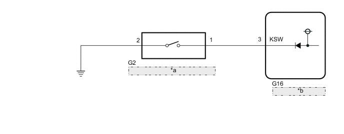
| *a | Unlock Warning Switch Assembly |
| *b | Transponder Key ECU Assembly |
CAUTION / NOTICE / HINT
Note
-
If the transponder key ECU assembly is replaced, refer to Service Bulletin.
-
After repair, confirm that no DTCs are output by performing "DTC Output Confirmation Operation".
PROCEDURE
-
CLEAR DTC
-
Clear the DTCs.
Body Electrical > Immobiliser > Clear DTCsResult Proceed to NEXT
NEXT 
-
-
CHECK FOR DTC
-
Check for DTCs.
Body Electrical > Immobiliser > Trouble CodesTech Tips
Before checking for DTCs, perform the "DTC Output Confirmation Operation" procedure.
OK DTC B2780 is not output. Result Result Proceed to B2780 is not output A B2780 is output B
A 
USE SIMULATION METHOD TO CHECK Click here
B
-
-
INSPECT UNLOCK WARNING SWITCH ASSEMBLY
-
Remove the unlock warning switch assembly.
-
Inspect the unlock warning switch assembly.
Result Proceed to OK NG
NG
REPLACE UNLOCK WARNING SWITCH ASSEMBLY Click here
OK
-
-
CHECK HARNESS AND CONNECTOR (UNLOCK WARNING SWITCH ASSEMBLY - TRANSPONDER KEY ECU ASSEMBLY AND BODY GROUND)
-
Disconnect the G2 unlock warning switch assembly connector.
-
Disconnect the G16 transponder key ECU assembly connector.
-
Measure the resistance according to the value(s) in the table below.
Standard Resistance Tester Connection Condition Specified Condition G2-1 - G16-3 (KSW) Always Below 1 Ω G2-2 - Body ground Always Below 1 Ω G2-1 - Body ground Always 10 kΩ or higher G16-3 (KSW) - Body ground Always 10 kΩ or higher Result Proceed to OK NG
OK
REPLACE TRANSPONDER KEY ECU ASSEMBLY
NG
REPAIR OR REPLACE HARNESS OR CONNECTOR
-