Click here
-
DATA LIST
Tip:Using the GTS to read the Data List allows the values or states of switches, sensors, actuators and other items to be read without removing any parts. This non-intrusive inspection can be very useful because intermittent conditions or signals may be discovered before parts or wiring is disturbed. Reading the Data List information early in troubleshooting is one way to save diagnostic time.
Note:In the table below, the values listed under "Normal Condition" are reference values. Do not depend solely on these reference values when deciding whether a part is faulty or not.
-
Connect the GTS to the DLC3.
-
Turn the ignition switch to ON.
-
Turn the GTS on.
-
Enter the following menus: Body Electrical / Immobiliser or Engine / Data List.
-
Read the Data List according to the display on the GTS.
- Body Electrical > Immobiliser > Data List
Tester Display Measurement Item Range Normal Condition Diagnostic Note D Door Courtesy SW Driver side courtesy switch signal ON or OFF ON: Driver door open
OFF: Driver door closed
for LHD Key SW Unlock warning switch signal ON or OFF ON: Key in ignition key cylinder
OFF: No key in ignition key cylinder
- IG SW Ignition switch signal ON or OFF ON: Ignition switch ON or engine started
OFF: Ignition switch ACC or off
- Immobiliser Immobiliser system status Set or Unset Set: No key in ignition key cylinder, or 20 seconds elapsed after turning the ignition switch to ACC or off
Unset: Key in ignition key cylinder
- Response Transponder chip data NG or OK NG: Data error
OK: Data OK
- Frame Error Transponder chip data NG or OK NG: Data error
OK: Data OK
- Different Serial Number Transponder chip data NG or OK NG: Data error
OK: Data OK
- Different Encrypt Code Transponder chip data NG or OK NG: Data error
OK: Data OK
- Abnormal Status Transponder chip data NG or OK NG: Data error
OK: Data OK
- Bcc Malfunction Transponder chip data NG or OK NG: Incorrect data being sent
OK: Correct data being sent
- Sub Key Sub key ID code signal Reg or Unreg Reg: Registered sub key ID code sent
Unreg: Unmatching sub key ID code sent
- Master Key Master key ID code signal Reg or Unreg Reg: Registered master key ID code sent
Unreg: Unmatching master key ID code sent
- Transponder S-code Number of registered sub key Min. 0, Max. 15 Number of registered sub key - Transponder M-code Number of registered master key Min. 0, Max. 15 Number of registered master key - Reg Code Space Full Key registration code memory space full No or Yes No: Possible to register more key codes
Yes: Cannot register any more key codes
- +B Power source Break or Normal Break: Power source open
Normal: Power source normal
- Antenna Coil Status Transponder key coil condition Normal or Fail Normal: Antenna coil normal
Fail: Antenna coil malfunctioning
- EEPROM Status EEPROM status NG or OK NG: Data error
OK: Data OK
- E/G Start Permission Engine start permission NG or OK NG: Engine start not permitted
OK: Engine start permitted
- Immobi ECU Comm Spd Immobiliser ECU communication speed Unknown, 50bps, 200bps or No Res Unknown: ECU communication speed unknown
50bps: ECU communication speed 50 bps
200bps: ECU communication speed 200 bps
No Res: No ECU communication response
- The Number of DTCs Number of DTCs Min.: 0, Max.: 255 Number of stored DTCs - -
-
Tip: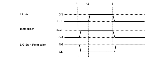
Data from an actual vehicle provided for reference.
-
*1: Insert a key into the ignition key cylinder and turn the ignition switch to ACC.
-
*2: Turn the ignition switch to ON.
-
*3: Turn the ignition switch off and remove the key from the ignition key cylinder.
- Powertrain > Engine > Data List
Tester Display Measurement Item Range Normal Condition Diagnostic Note Immobiliser Fuel Cut Status of immobiliser system fuel cut* ON or OFF - - -
-
-
*: for SFI System
- Body Electrical > Immobiliser > Data List
-
-
ACTIVE TEST
Tip:Using the GTS to perform Active Tests allows relays, VSVs, actuators and other items to be operated without removing any parts. This non-intrusive functional inspection can be very useful because intermittent operation may be discovered before parts or wiring is disturbed. Performing Active Tests early in troubleshooting is one way to save diagnostic time. Data List information can be displayed while performing Active Tests.
-
Connect the GTS to the DLC3.
-
Turn the ignition switch to ON.
-
Turn the GTS on.
-
Enter the following menus: Body Electrical / Immobiliser / Active Test.
-
Perform the Active Test according to the display on the GTS.
- Body Electrical > Immobiliser > Active Test
Tester Display Measurement Item Control Range Diagnostic Note Security Indicator Theft warning indicator light assembly ON/OFF - -
-
- Body Electrical > Immobiliser > Active Test
-