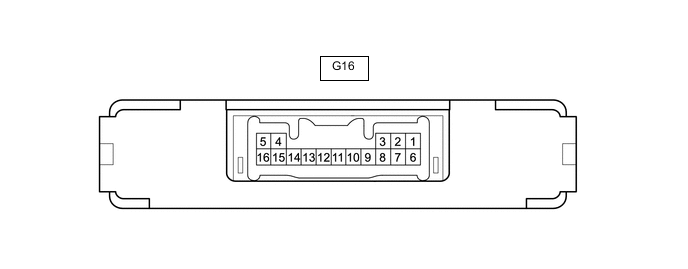
IMMOBILISER SYSTEM(w/o Entry and Start System) TERMINALS OF ECU
-
CHECK TRANSPONDER KEY ECU ASSEMBLY
-
Disconnect the G16 transponder key ECU assembly connector.
-
Measure the resistance and voltage according to the value(s) in the table below.
Tech Tips
Measure the values on the wire harness side with the connector disconnected.
Tester Connection Input/Output Wiring Color Terminal Description Condition Specified Condition Related Data List Item G16-5 (GND) - Body ground - BR - Body ground Ground Always Below 1 Ω - G16-1 (+B) - G16-5 (GND) Input L - BR Battery Always 11 to 14 V +B G16-2 (IG) - G16-5 (GND) Input P - BR Ignition switch Ignition switch off Below 1 V IG SW Ignition switch ON 11 to 14 V G16-3 (KSW) - G16-5 (GND) Input G - BR Unlock warning switch signal No key in ignition key cylinder 10 kΩ or higher Key SW/B2780 Key in ignition key cylinder Below 1 Ω If the result is not as specified, there may be a malfunction on the wire harness side.
-
Reconnect the G16 transponder key ECU assembly connector.
-
Measure the voltage and check for pulses according to the value(s) in the table below.
Tester Connection Input/Output Wiring Color Terminal Description Condition Specified Condition Related Data List Item G16-8 (IND) - G16-5 (GND) Output Y - BR Security indicator light signal No key in ignition key cylinder, or 20 seconds elapsed after turning ignition switch to ACC or off (immobiliser system set) Pulse generation Immobiliser Key in ignition key cylinder (immobiliser system unset) Below 1 V G16-9 (D) - G16-5 (GND) Input/Output R - BR DLC3 communication Without communication Below 1 V - During communication Pulse generation G16-4 (ANT1) - G16-5 (GND) Input/Output Y - BR Transponder key amplifier power source No key in ignition key cylinder 4 to 6 V - Within 3 seconds of inserting key into ignition key cylinder Pulse generation
(See waveform 1)
G16-15 (ANT2) - G16-5 (GND) Input/Output W - BR Transponder key amplifier communication signal No key in ignition key cylinder 4 to 6 V - Within 3 seconds of inserting key into ignition key cylinder Pulse generation
(See waveform 2)
G16-12 (EFII) - G16-5 (GND) Input Y - BR ECM input signal Within 3 seconds of starter operation and initial combustion, or within 3 seconds of ignition switch first being turned to ON after cable disconnected and reconnected to negative (-) battery terminal Pulse generation
(See waveform 3)
E/G Start Permission G16-13 (EFIO) - G16-5 (GND) Output B - BR ECM output signal Ignition switch off Below 1 V E/G Start Permission Within 3 seconds of starter operation and initial combustion, or within 3 seconds of ignition switch first being turned to ON after cable disconnected and reconnected to negative (-) battery terminal Pulse generation
(See waveform 4)
-
Using an oscilloscope, check the waveform.
-
Waveform 1 (Reference)
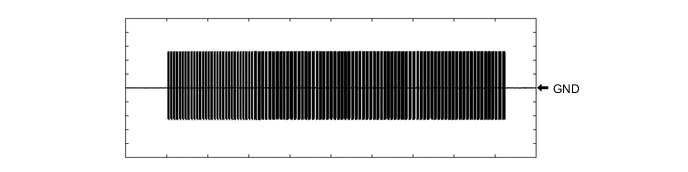
Tester Connection G16-4 (ANT1) - G16-5 (GND) Tool Setting 2 V/DIV., 2 s./DIV. Condition Within 3 seconds of inserting key into ignition key cylinder -
Waveform 2 (Reference)
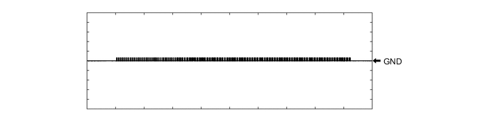
Tester Connection G16-15 (ANT2) - G16-5 (GND) Tool Setting 2 V/DIV., 2 s./DIV. Condition Within 3 seconds of inserting key into ignition key cylinder -
Waveform 3 (Reference)
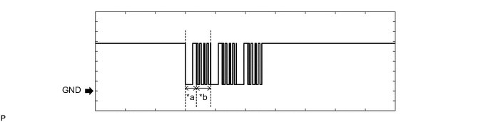
*a Approximately 160 ms *b Approximately 270 ms Tester Connection G16-12 (EFII) - G16-5 (GND) Tool Setting 2 V/DIV., 500 ms./DIV. Condition Within 3 seconds of starter operation and initial combustion, or within 3 seconds of ignition switch first being turned to ON after cable disconnected and reconnected to negative (-) battery terminal -
Waveform 4 (Reference)

*a Approximately 160 ms *b Approximately 270 ms Tester Connection G16-13 (EFIO) - G16-5 (GND) Tool Setting 2 V/DIV., 500 ms./DIV. Condition Within 3 seconds of starter operation and initial combustion, or within 3 seconds of ignition switch first being turned to ON after cable disconnected and reconnected to negative (-) battery terminal
-
-
-
CHECK ECM (for 1TR-FE, 2TR-FE)
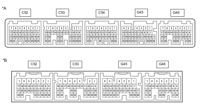
*A for Automatic Transmission Models *B for Manual Transmission Models
-
Measure the resistance, voltage and check for pulses according to the value(s) in the table below.
Tester Connection Input/Output Wiring Color Terminal Description Condition Specified Condition Related Data List Item C52-3 (E1) - Body ground - W-B - Body ground Ground Always Below 1 Ω - C52-4 (ME01) - Body ground - W-B - Body ground Ground Always Below 1 Ω - C52-1 (E01) - Body ground - W-B - Body ground Ground Always Below 1 Ω - C53-5 (E04) - Body ground - W-B - Body ground Ground Always Below 1 Ω - C52-2 (E02) - Body ground - W-B - Body ground Ground Always Below 1 Ω - G46-1 (+B) - C52-3 (E1) Input L - W-B +B power supply Ignition switch ON 11 to 14 V - G46-2 (+B2) - C52-3 (E1) Input B - W-B +B power supply Ignition switch ON 11 to 14 V - G46-3 (BATT) - C52-3 (E1) Input Y - W-B +B power supply Always 11 to 14 V - G45-9 (IMO) - C52-3 (E1) Output Y - W-B Transponder key ECU assembly output signal Ignition switch off 11 to 14 V E/G Start Permission Within 3 seconds of starter operation and initial combustion, or within 3 seconds of ignition switch first being turned to ON after cable disconnected and reconnected to negative (-) battery terminal Pulse generation
(See waveform 1)
E/G Start Permission G45-10 (IMI) - C52-3 (E1) Input B - W-B Transponder key ECU assembly input signal Ignition switch off Below 1 V E/G Start Permission Within 3 seconds of starter operation and initial combustion, or within 3 seconds of ignition switch first being turned to ON after cable disconnected and reconnected to negative (-) battery terminal Pulse generation
(See waveform 2)
E/G Start Permission -
Using an oscilloscope, check the waveform.
-
Waveform 1 (Reference)
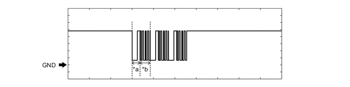
*a Approximately 160 ms *b Approximately 270 ms Tester Connection G45-9 (IMO) - C52-3 (E1) Tool Setting 2 V/DIV., 500 ms./DIV. Condition Within 3 seconds of starter operation and initial combustion, or within 3 seconds of ignition switch first being turned to ON after cable disconnected and reconnected to negative (-) battery terminal -
Waveform 2 (Reference)
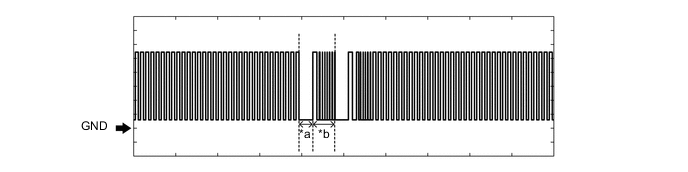
*a Approximately 160 ms *b Approximately 270 ms Tester Connection G45-10 (IMI) - C52-3 (E1) Tool Setting 2 V/DIV., 500 ms./DIV. Condition Within 3 seconds of starter operation and initial combustion, or within 3 seconds of ignition switch first being turned to ON after cable disconnected and reconnected to negative (-) battery terminal
-
-
-
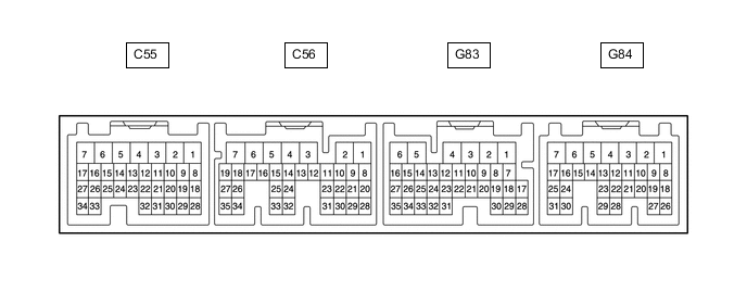
CHECK ECM (for 2KD-FTV)
-
Measure the resistance, voltage and check for pulses according to the value(s) in the table below.
Terminal No. (Symbol) Input/Output Wiring Color Terminal Description Condition Specified Condition Related Data List Item/DTC C56-7 (E1) - Body ground - W-B - Body ground Ground Always Below 1 Ω - C55-7 (E01) - Body ground - W-B - Body ground Ground Always Below 1 Ω - C55-6 (E02) - Body ground - W-B - Body ground Ground Always Below 1 Ω - G83-2 (BATT) - C56-7 (E1) Input Y - W-B +B power supply Always 11 to 14 V - G84-1 (+B) - C56-7 (E1) Input L - W-B +B power supply Ignition switch ON 11 to 14 V - G83-29 (IMO) - C56-7 (E1) Output Y - W-B Transponder key ECU assembly output signal Ignition switch off 11 to 14 V - Within 3 seconds of starter operation and initial combustion, or within 3 seconds of ignition switch first being turned to ON after cable disconnected and reconnected to negative (-) battery terminal Pulse generation
(See waveform 1)
- G83-30 (IMI) - C56-7 (E1) Input B - W-B Transponder key ECU assembly input signal Ignition switch off Below 1 V - Within 3 seconds of starter operation and initial combustion, or within 3 seconds of ignition switch first being turned to ON after cable disconnected and reconnected to negative (-) battery terminal Pulse generation
(See waveform 2)
- -
Using an oscilloscope, check the waveform.
Tech Tips
The waveform shown in the illustration is an example for reference only. Noise, chattering, etc. are not shown.
-
Waveform 1 (Reference)

*a Approximately 160 ms *b Approximately 270 ms Measurement Condition Item Content Tester Connection G83-29 (IMO) - C56-7 (E1) Tool Setting 2 V/DIV., 500 ms./DIV. Condition Within 3 seconds of starter operation and initial combustion, or within 3 seconds of ignition switch first being turned to ON after cable disconnected and reconnected to negative (-) battery terminal -
Waveform 2 (Reference)

*a Approximately 160 ms *b Approximately 270 ms Measurement Condition Item Content Tester Connection G83-30 (IMI) - C56-7 (E1) Tool Setting 2 V/DIV., 500 ms./DIV. Condition Within 3 seconds of starter operation and initial combustion, or within 3 seconds of ignition switch first being turned to ON after cable disconnected and reconnected to negative (-) battery terminal
-
-
-
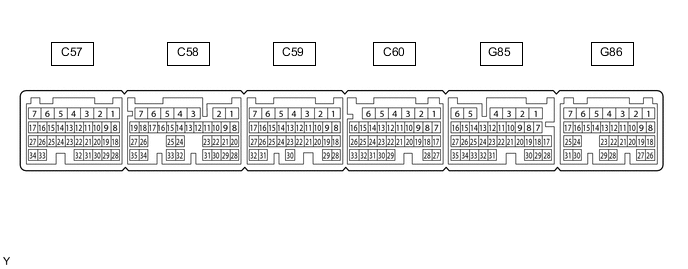
CHECK ECM (for 1GD-FTV, 2GD-FTV)
-
Measure the resistance, voltage and check for pulses according to the value(s) in the table below.
Terminal No. (Symbol) Input/Output Wiring Color Terminal Description Condition Specified Condition Related Data List Item/DTC C60-1 (E1) - Body ground - W-B - Body ground Ground Always Below 1 Ω - C60-3 (ME01) - Body ground - W-B - Body ground Ground Always Below 1 Ω - C59-3 (E01) - Body ground - W-B - Body ground Ground Always Below 1 Ω - C60-4 (E02) - Body ground - W-B - Body ground Ground Always Below 1 Ω - C60-2 (E04) - Body ground - W-B - Body ground Ground Always Below 1 Ω - G86-1 (BATT) - C60-1 (E1) Input Y - W-B +B power supply Always 11 to 14 V - G86-2 (+B) - C60-1 (E1) Input L - W-B +B power supply Ignition switch ON 11 to 14 V - G86-3 (+B2) - C60-1 (E1) Input B - W-B +B power supply Ignition switch ON 11 to 14 V - G86-17 (IMO) - C60-1 (E1) Output Y - W-B Transponder key ECU assembly output signal Ignition switch off 11 to 14 V - Within 3 seconds of starter operation and initial combustion, or within 3 seconds of ignition switch first being turned to ON after cable disconnected and reconnected to negative (-) battery terminal Pulse generation
(See waveform 1)
- G86-16 (IMI) - C60-1 (E1) Input B - W-B Transponder key ECU assembly input signal Ignition switch off Below 1 V - Within 3 seconds of starter operation and initial combustion, or within 3 seconds of ignition switch first being turned to ON after cable disconnected and reconnected to negative (-) battery terminal Pulse generation
(See waveform 2)
- -
Using an oscilloscope, check the waveform.
Tech Tips
The waveform shown in the illustration is an example for reference only. Noise, chattering, etc. are not shown.
-
Waveform 1 (Reference)
*a Approximately 160 ms *b Approximately 270 ms Measurement Condition Item Content Tester Connection G86-17 (IMO) - C60-1 (E1) Tool Setting 2 V/DIV., 500 ms./DIV. Condition Within 3 seconds of starter operation and initial combustion, or within 3 seconds of ignition switch first being turned to ON after cable disconnected and reconnected to negative (-) battery terminal -
Waveform 2 (Reference)
*a Approximately 160 ms *b Approximately 270 ms Measurement Condition Item Content Tester Connection G86-16 (IMI) - C60-1 (E1) Tool Setting 2 V/DIV., 500 ms./DIV. Condition Within 3 seconds of starter operation and initial combustion, or within 3 seconds of ignition switch first being turned to ON after cable disconnected and reconnected to negative (-) battery terminal
-
-
-
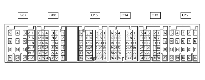
CHECK ECM (for 1GR-FE)
-
Measure the resistance, voltage and check for pulses according to the value(s) in the table below.
Tester Connection Input/Output Wiring Color Terminal Description Condition Specified Condition Related Data List Item C13-12 (E1) - Body ground - BR - Body ground Ground Always Below 1 Ω - C13-29 (ME01) - Body ground - W-B - Body ground Ground Always Below 1 Ω - C13-23 (E01) - Body ground - W-B - Body ground Ground Always Below 1 Ω - C12-16 (E04) - Body ground - W-B - Body ground Ground Always Below 1 Ω - C12-14 (E02) - Body ground - W-B - Body ground Ground Always Below 1 Ω - G87-23 (+B) - C13-12 (E1) Input L - BR +B power supply Ignition switch ON 11 to 14 V - G87-22 (+B2) - C13-12 (E1) Input B - BR +B power supply Ignition switch ON 11 to 14 V - G87-24 (BATT) - C13-12 (E1) Input Y - BR +B power supply Always 11 to 14 V - G88-8 (IMO) - C13-12 (E1) Output Y - BR Transponder key ECU assembly output signal Ignition switch off 11 to 14 V E/G Start Permission Within 3 seconds of starter operation and initial combustion, or within 3 seconds of ignition switch first being turned to ON after cable disconnected and reconnected to negative (-) battery terminal Pulse generation
(See waveform 1)
E/G Start Permission G88-10 (IMI) - C13-12 (E1) Input B - BR Transponder key ECU assembly input signal Ignition switch off Below 1 V E/G Start Permission Within 3 seconds of starter operation and initial combustion, or within 3 seconds of ignition switch first being turned to ON after cable disconnected and reconnected to negative (-) battery terminal Pulse generation
(See waveform 2)
E/G Start Permission -
Using an oscilloscope, check the waveform.
-
Waveform 1 (Reference)
*a Approximately 160 ms *b Approximately 270 ms Tester Connection G88-8 (IMO) - C13-12 (E1) Tool Setting 2 V/DIV., 500 ms./DIV. Condition Within 3 seconds of starter operation and initial combustion, or within 3 seconds of ignition switch first being turned to ON after cable disconnected and reconnected to negative (-) battery terminal -
Waveform 2 (Reference)
*a Approximately 160 ms *b Approximately 270 ms Tester Connection G88-10 (IMI) - C13-12 (E1) Tool Setting 2 V/DIV., 500 ms./DIV. Condition Within 3 seconds of starter operation and initial combustion, or within 3 seconds of ignition switch first being turned to ON after cable disconnected and reconnected to negative (-) battery terminal
-
-
-
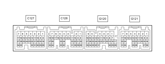
CHECK ECM (for 5L-E)
-
Measure the resistance, voltage and check for pulses according to the value(s) in the table below.
Terminal No. (Symbol) Input/Output Wiring Color Terminal Description Condition Specified Condition Related Data List Item/DTC C127-5 (E1) - Body ground - BR - Body ground Ground Always Below 1 Ω - C127-7 (E01) - Body ground - W-B - Body ground Ground Always Below 1 Ω - C127-6 (E02) - Body ground - W-B - Body ground Ground Always Below 1 Ω - G121-2 (BATT) - C127-5 (E1) Input Y - BR +B power supply Always 11 to 14 V - G121-1 (+B) - C127-5 (E1) Input L - BR +B power supply Ignition switch ON 11 to 14 V - G120-18 (IMO) - C127-5 (E1) Output Y - BR Transponder key ECU assembly output signal Ignition switch off 11 to 14 V - Within 3 seconds of starter operation and initial combustion, or within 3 seconds of ignition switch first being turned to ON after cable disconnected and reconnected to negative (-) battery terminal Pulse generation
(See waveform 1)
- G120-19 (IMI) - C127-5 (E1) Input B - BR Transponder key ECU assembly input signal Ignition switch off Below 1 V - Within 3 seconds of starter operation and initial combustion, or within 3 seconds of ignition switch first being turned to ON after cable disconnected and reconnected to negative (-) battery terminal Pulse generation
(See waveform 2)
- -
Using an oscilloscope, check the waveform.
Tech Tips
The waveform shown in the illustration is an example for reference only. Noise, chattering, etc. are not shown.
-
Waveform 1 (Reference)
*a Approximately 160 ms *b Approximately 270 ms Measurement Condition Item Content Tester Connection G120-18 (IMO) - C127-5 (E1) Tool Setting 2 V/DIV., 500 ms./DIV. Condition Within 3 seconds of starter operation and initial combustion, or within 3 seconds of ignition switch first being turned to ON after cable disconnected and reconnected to negative (-) battery terminal -
Waveform 2 (Reference)
*a Approximately 160 ms *b Approximately 270 ms Measurement Condition Item Content Tester Connection G120-19 (IMI) - C127-5 (E1) Tool Setting 2 V/DIV., 500 ms./DIV. Condition Within 3 seconds of starter operation and initial combustion, or within 3 seconds of ignition switch first being turned to ON after cable disconnected and reconnected to negative (-) battery terminal
-
-