DOOR CONTROL RELAY ON-VEHICLE INSPECTION
CAUTION / NOTICE / HINT
Tech Tips
-
Use the same procedure for RHD and LHD vehicles.
-
The procedures listed below are for LHD vehicles.
PROCEDURE
-
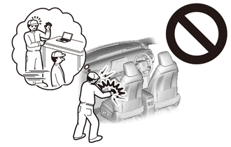
PRECAUTION (w/ Airbag System)
CAUTION:
Be sure to read Precaution thoroughly before servicing.
for Type A:
for Type B:
Note
After turning the ignition switch off, waiting time may be required before disconnecting the cable from the negative (-) battery terminal. Therefore, make sure to read the disconnecting the cable from the negative (-) battery terminal notice before proceeding with work.
-
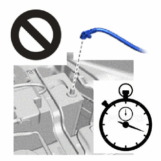
DISCONNECT CABLE FROM NEGATIVE BATTERY TERMINAL (w/ Airbag System)
CAUTION:
-
Wait at least 90 seconds after disconnecting the cable from the negative (-) battery terminal to disable the SRS system.
-
If the airbag deploys for any reason, it may cause a serious accident.
Note
When disconnecting the cable, some systems need to be initialized after the cable is reconnected.
-
-
REMOVE STEERING WHEEL ASSEMBLY
-
REMOVE INSTRUMENT CLUSTER FINISH PANEL ASSEMBLY
-
REMOVE CONTROL KNOB SUB-ASSEMBLY
-
for Manual Cooler System:
-
for Manual Air Conditioning System:
-
-
REMOVE AIR INLET DAMPER CONTROL LEVER
-
for Manual Cooler System:
-
for Manual Air Conditioning System:
-
-
REMOVE INTEGRATION PANEL SUB-ASSEMBLY
-
for Manual Cooler System:
-
for Manual Air Conditioning System:
-
-
REMOVE AIR CONDITIONING CONTROL ASSEMBLY (for Automatic Air Conditioning System)
-
REMOVE DOOR LOCK CONTROL RELAY (for LHD)
-
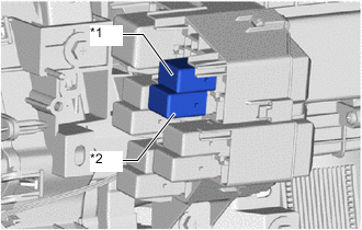
*1 No. 1 Door Lock Control Relay *2 No. 2 Door Lock Control Relay Remove the door lock control relay.
-
-
REMOVE DOOR LOCK CONTROL RELAY (for RHD)
-
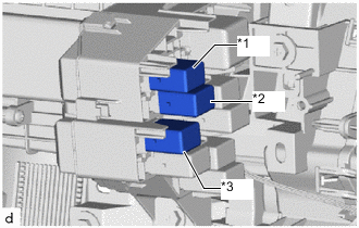
*1 No. 1 Door Lock Control Relay *2 No. 2 Door Lock Control Relay *3 No. 3 Door Lock Control Relay Remove the door lock control relay.
-
-
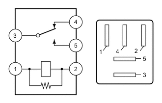
INSPECT NO. 1 DOOR LOCK CONTROL RELAY
-

Inspect the No. 1 door lock control relay.
-
Measure the resistance according to the value(s) in the table below.
Standard Resistance Tester Connection Condition Specified Condition 3 - 4 Battery voltage is not applied to terminals 1 and 2 Below 1 Ω Battery voltage is applied to terminals 1 and 2 10 kΩ or higher 3 - 5 Battery voltage is not applied to terminals 1 and 2 10 kΩ or higher Battery voltage is applied to terminals 1 and 2 Below 1 Ω If the result is not as specified, replace the No. 1 door lock control relay.
-
-
-
INSPECT NO. 2 DOOR LOCK CONTROL RELAY
-
Inspect the No. 2 door lock control relay.
-
Measure the resistance according to the value(s) in the table below.
Standard Resistance Tester Connection Condition Specified Condition 3 - 4 Battery voltage is not applied to terminals 1 and 2 Below 1 Ω Battery voltage is applied to terminals 1 and 2 10 kΩ or higher 3 - 5 Battery voltage is not applied to terminals 1 and 2 10 kΩ or higher Battery voltage is applied to terminals 1 and 2 Below 1 Ω If the result is not as specified, replace the No. 2 door lock control relay.
-
-
-
INSPECT NO. 3 DOOR LOCK CONTROL RELAY (w/ Double Locking System)
-

Inspect the No. 3 door lock control relay.
-
Measure the resistance according to the value(s) in the table below.
Standard Resistance Tester Connection Condition Specified Condition 3 - 4 Battery voltage is not applied to terminals 1 and 2 Below 1 Ω Battery voltage is applied to terminals 1 and 2 10 kΩ or higher 3 - 5 Battery voltage is not applied to terminals 1 and 2 10 kΩ or higher Battery voltage is applied to terminals 1 and 2 Below 1 Ω If the result is not as specified, replace the No. 3 door lock control relay.
-
-
-
INSTALL DOOR LOCK CONTROL RELAY (for LHD)
-

*1 No. 1 Door Lock Control Relay *2 No. 2 Door Lock Control Relay Install the door lock control relay.
-
-
INSTALL DOOR LOCK CONTROL RELAY (for RHD)
-
*1 No. 1 Door Lock Control Relay *2 No. 2 Door Lock Control Relay *3 No. 3 Door Lock Control Relay Remove the door lock control relay.
-
-
INSTALL INTEGRATION PANEL SUB-ASSEMBLY
-
for Manual Cooler System:
-
for Manual Air Conditioning System:
-
-
INSTALL AIR INLET DAMPER CONTROL LEVER
-
for Manual Cooler System:
-
for Manual Air Conditioning System:
-
-
INSTALL CONTROL KNOB SUB-ASSEMBLY
-
for Manual Cooler System:
-
for Manual Air Conditioning System:
-
-
INSTALL AIR CONDITIONING CONTROL ASSEMBLY (for Automatic Air Conditioning System)
-
INSTALL INSTRUMENT CLUSTER FINISH PANEL ASSEMBLY
-
INSTALL STEERING WHEEL ASSEMBLY
-
CONNECT CABLE TO NEGATIVE BATTERY TERMINAL (w/ Airbag System)
Note
When disconnecting the cable, some systems need to be initialized after the cable is reconnected.
-
CHECK SRS WARNING LIGHT (w/ Airbag System)
for Type A:
for Type B: