PROCEDURE
- Click here
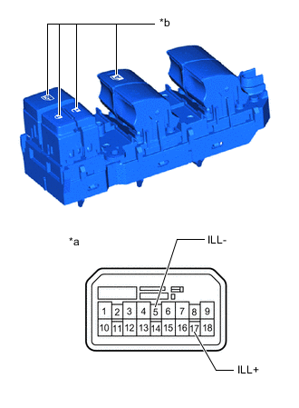
INSPECT POWER WINDOW REGULATOR MASTER SWITCH ASSEMBLY (for Double Cab, LHD)
-
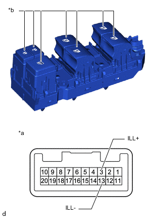
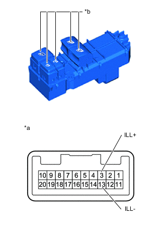
*a Component without harness connected
(Power Window Regulator Master Switch Assembly)
*b LED Illumination Check that the LED illuminates. (w/ Entry and Start System)
-
Apply battery voltage to the power window regulator master switch assembly and check that the LED illuminates.
OK Battery connection Result Battery positive (+) - 3 (ILL+)
Battery negative (-) - 13 (ILL-)
LED illuminates If the result is not as specified, replace the power window regulator master switch assembly.
-
-

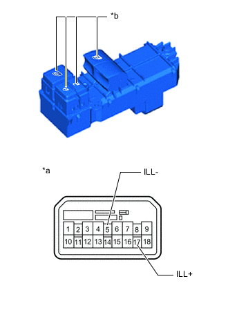
*a Component without harness connected
(Power Window Regulator Master Switch Assembly)
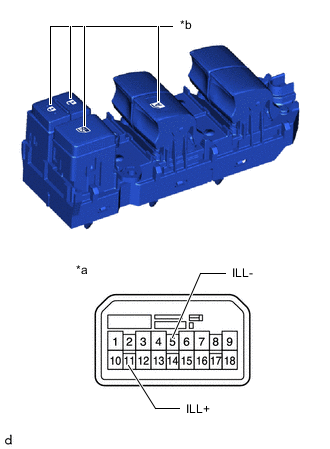
*b LED Illumination Check that the LED illuminates. (for Models with Jam Protection Function on Driver Door Window Only)
-
Apply battery voltage to the power window regulator master switch assembly and check that the LED illuminates.
OK Battery connection Result Battery positive (+) - 11 (ILL+)
Battery negative (-) - 5 (ILL-)
LED illuminates If the result is not as specified, replace the power window regulator master switch assembly.
-
-
*a Component without harness connected
(Power Window Regulator Master Switch Assembly)
*b LED Illumination Check that the LED illuminates. (w/o Jam Protection Function)
-
Apply battery voltage to the power window regulator master switch assembly and check that the LED illuminates.
OK Battery connection Result Battery positive (+) - 11 (ILL+)
Battery negative (-) - 5 (ILL-)
LED illuminates If the result is not as specified, replace the power window regulator master switch assembly.
-
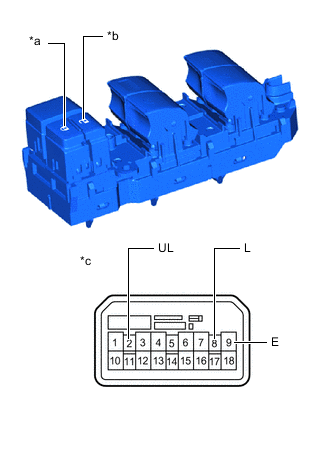
-
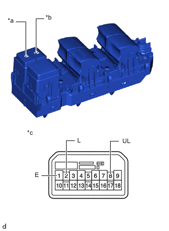
*a Lock *b Unlock *c Component without harness connected
(Power Window Regulator Master Switch Assembly)
Measure the resistance according to the value(s) in the table below. (w/o Entry and Start System)
Standard Resistance Tester Connection Condition Specified Condition 2 (L) - 1 (E) Lock switch pushed Below 1 Ω 2 (L) - 1 (E) Lock switch not pushed 10 kΩ or higher 8 (UL) - 1 (E) Unlock switch pushed Below 1 Ω 8 (UL) - 1 (E) Unlock switch not pushed 10 kΩ or higher If the result is not as specified, replace the power window regulator master switch assembly.
-
- Click here
INSPECT POWER WINDOW REGULATOR MASTER SWITCH ASSEMBLY (for Double Cab, RHD)
-
*a Component without harness connected
(Power Window Regulator Master Switch Assembly)
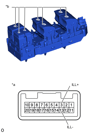
*b LED Illumination Check that the LED illuminates. (w/ Entry and Start System)
-
Apply battery voltage to the power window regulator master switch assembly and check that the LED illuminates.
OK Battery connection Result Battery positive (+) - 3 (ILL+)
Battery negative (-) - 13 (ILL-)
LED illuminates If the result is not as specified, replace the power window regulator master switch assembly.
-
-
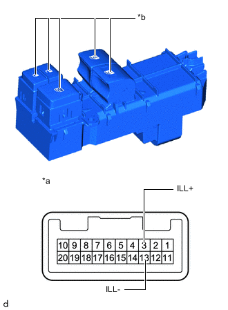
*a Component without harness connected
(Power Window Regulator Master Switch Assembly)
*b LED Illumination Check that the LED illuminates. (for Models with Jam Protection Function on Driver Door Window Only)
-
Apply battery voltage to the power window regulator master switch assembly and check that the LED illuminates.
OK Battery connection Result Battery positive (+) - 17 (ILL+)
Battery negative (-) - 5 (ILL-)
LED illuminates If the result is not as specified, replace the power window regulator master switch assembly.
-
-

*a Component without harness connected
(Power Window Regulator Master Switch Assembly)
*b LED Illumination Check that the LED illuminates. (w/o Jam Protection Function)
-
Apply battery voltage to the power window regulator master switch assembly and check that the LED illuminates.
OK Battery connection Result Battery positive (+) - 17 (ILL+)
Battery negative (-) - 5 (ILL-)
LED illuminates If the result is not as specified, replace the power window regulator master switch assembly.
-
-
*a Lock *b Unlock *c Component without harness connected
(Power Window Regulator Master Switch Assembly)
Measure the resistance according to the value(s) in the table below. (w/o Entry and Start System)
Standard Resistance Tester Connection Condition Specified Condition 8 (L) - 9 (E) Lock switch pushed Below 1 Ω 8 (L) - 9 (E) Lock switch not pushed 10 kΩ or higher 2 (UL) - 9 (E) Unlock switch pushed Below 1 Ω 2 (UL) - 9 (E) Unlock switch not pushed 10 kΩ or higher If the result is not as specified, replace the power window regulator master switch assembly.
-
- Click here
INSPECT POWER WINDOW REGULATOR MASTER SWITCH ASSEMBLY (for Single Cab, Smart Cab, LHD)
-
*a Component without harness connected
(Power Window Regulator Master Switch Assembly)
*b LED Illumination Check that the LED illuminates. (w/ Entry and Start System)
-
Apply battery voltage to the power window regulator master switch assembly and check that the LED illuminates.
OK Battery connection Result Battery positive (+) - 3 (ILL+)
Battery negative (-) - 13 (ILL-)
LED illuminates If the result is not as specified, replace the power window regulator master switch assembly.
-
-
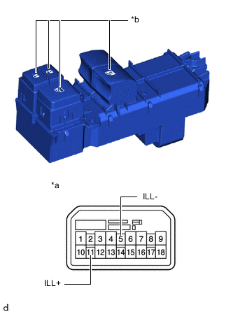
*a Component without harness connected
(Power Window Regulator Master Switch Assembly)
*b LED Illumination Check that the LED illuminates. (for Models with Jam Protection Function on Driver Door Window Only)
-
Apply battery voltage to the power window regulator master switch assembly and check that the LED illuminates.
OK Battery connection Result Battery positive (+) - 11 (ILL+)
Battery negative (-) - 5 (ILL-)
LED illuminates If the result is not as specified, replace the power window regulator master switch assembly.
-
-

*a Component without harness connected
(Power Window Regulator Master Switch Assembly)
*b LED Illumination Check that the LED illuminates. (w/o Jam Protection Function)
-
Apply battery voltage to the power window regulator master switch assembly and check that the LED illuminates.
OK Battery connection Result Battery positive (+) - 11 (ILL+)
Battery negative (-) - 5 (ILL-)
LED illuminates If the result is not as specified, replace the power window regulator master switch assembly.
-
-

*a Lock *b Unlock *c Component without harness connected
(Power Window Regulator Master Switch Assembly)
Measure the resistance according to the value(s) in the table below. (w/o Entry and Start System)
Standard Resistance Tester Connection Condition Specified Condition 2 (L) - 1 (E) Lock switch pushed Below 1 Ω 2 (L) - 1 (E) Lock switch not pushed 10 kΩ or higher 8 (UL) - 1 (E) Unlock switch pushed Below 1 Ω 8 (UL) - 1 (E) Unlock switch not pushed 10 kΩ or higher If the result is not as specified, replace the power window regulator master switch assembly.
-
- Click here
INSPECT POWER WINDOW REGULATOR MASTER SWITCH ASSEMBLY (for Single Cab, Smart Cab , RHD)
-
*a Component without harness connected
(Power Window Regulator Master Switch Assembly)
*b LED Illumination Check that the LED illuminates. (w/ Entry and Start System)
-
Apply battery voltage to the power window regulator master switch assembly and check that the LED illuminates.
OK Battery connection Result Battery positive (+) - 3 (ILL+)
Battery negative (-) - 13 (ILL-)
LED illuminates If the result is not as specified, replace the power window regulator master switch assembly.
-
-
*a Component without harness connected
(Power Window Regulator Master Switch Assembly)
*b LED Illumination Check that the LED illuminates. (for Models with Jam Protection Function on Driver Door Window Only)
-
Apply battery voltage to the power window regulator master switch assembly and check that the LED illuminates.
OK Battery connection Result Battery positive (+) - 17 (ILL+)
Battery negative (-) - 5 (ILL-)
LED illuminates If the result is not as specified, replace the power window regulator master switch assembly.
-
-
*a Component without harness connected
(Power Window Regulator Master Switch Assembly)
*b LED Illumination Check that the LED illuminates. (w/o Jam Protection Function)
-
Apply battery voltage to the power window regulator master switch assembly and check that the LED illuminates.
OK Battery connection Result Battery positive (+) - 17 (ILL+)
Battery negative (-) - 5 (ILL-)
LED illuminates If the result is not as specified, replace the power window regulator master switch assembly.
-
-

*a Lock *b Unlock *c Component without harness connected
(Power Window Regulator Master Switch Assembly)
Measure the resistance according to the value(s) in the table below. (w/o Entry and Start System)
Standard Resistance Tester Connection Condition Specified Condition 8 (L) - 9 (E) Lock switch pushed Below 1 Ω 8 (L) - 9 (E) Lock switch not pushed 10 kΩ or higher 2 (UL) - 9 (E) Unlock switch pushed Below 1 Ω 2 (UL) - 9 (E) Unlock switch not pushed 10 kΩ or higher If the result is not as specified, replace the power window regulator master switch assembly.
-