KEY REMINDER WARNING SYSTEM TERMINALS OF ECU
-
CHECK COMBINATION METER ASSEMBLY
-
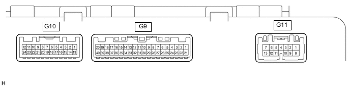
Measure the voltage and resistance according to the value(s) in the table below.
Tester Connection Wiring Color Terminal Description Condition Specified Condition G9-11 (KSW) - Body ground G - Body ground Unlock warning switch signal No key in ignition key cylinder 11 to 14 V Key in ignition key cylinder Below 1 V G9-21 (B) - Body ground W - Body ground Battery Always 11 to 14 V G9-22 (IG+) - Body ground Y - Body ground Ignition switch signal Ignition switch ON 11 to 14 V Ignition switch off Below 1 V G9-27 (EP) - Body ground W-B - Body ground Ground Always Below 1 Ω G10-15 (DCTY) - Body ground B - Body ground Driver side door condition signal Driver side door closed 11 to 14 V Driver side door open Below 1 V
-