WIRELESS DOOR LOCK CONTROL SYSTEM(w/o Entry and Start System) No Answer-Back
DESCRIPTION
In some cases, wireless door lock control functions are normal but the hazard warning light answer-back function does not operate. In such cases, hazard warning light signal outputs from the body ECU may be malfunctioning.
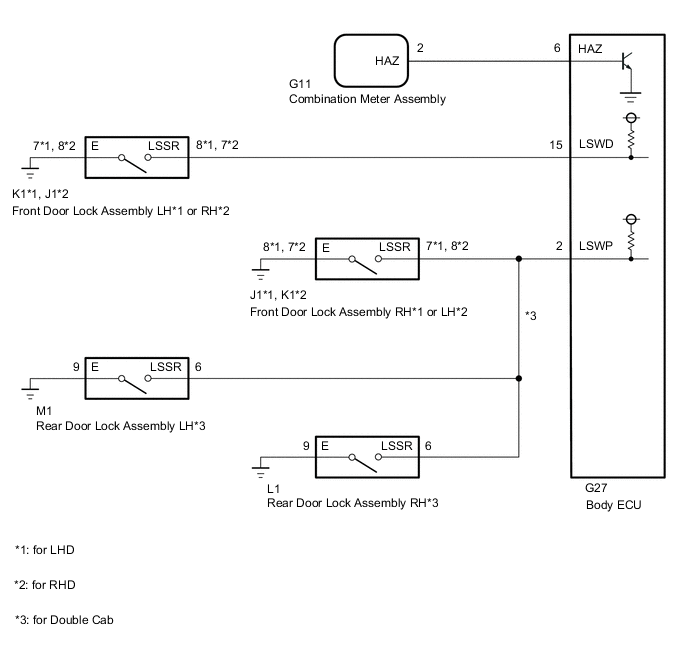
WIRING DIAGRAM
CAUTION / NOTICE / HINT
Note
-
If the body ECU has been replaced, it is necessary to initialize the body ECU.*1
-
As the door control battery is installed between the vehicle battery and body ECU, first perform the inspections to confirm that there are no malfunctions in the power source circuit for the body ECU before performing this troubleshooting procedure.*2
-
*1: w/ Automatic Light Control System
-
*2: w/ Door Control Battery
PROCEDURE
-
CHECK HAZARD WARNING LIGHTS OPERATION
-
Check that the hazard warning light blinks when the hazard warning signal switch is pressed.
OK Hazard warning light signal is normal. Result Proceed to OK NG
NG 
GO TO LIGHTING SYSTEM (PROCEED TO HAZARD WARNING SWITCH CIRCUIT) Click here
OK 
-
-
CHECK HARNESS AND CONNECTOR (COMBINATION METER ASSEMBLY - BODY ECU)
-
Disconnect the G11 combination meter assembly connector.
-
Disconnect the G27 body ECU connector.
-
Measure the resistance according to the value(s) in the table below.
Standard Resistance Tester Connection Condition Specified Condition G11-2 (HAZ) - G27-6 (HAZ) Always Below 1 Ω G11-2 (HAZ) or G27-6 (HAZ) - Body ground Always 10 kΩ or higher Result Proceed to OK NG
NG
REPAIR OR REPLACE HARNESS OR CONNECTOR
OK
-
-
INSPECT DOOR LOCK ASSEMBLY (DETECTION UNLOCK SWITCH)
*: for Double Cab
-
for Front Side:
-
Remove the front door lock assembly.
-
Inspect the front door lock assembly.
-
-
for Rear Side*:
-
Remove the rear door lock assembly.
-
Inspect the rear door lock assembly.
Result Result Proceed to OK A NG (for Front Side) B NG (for Rear Side) C -
B
REPLACE FRONT DOOR LOCK ASSEMBLY Click here
C
REPLACE REAR DOOR LOCK ASSEMBLY Click here
A
-
-
CHECK HARNESS AND CONNECTOR (DOOR LOCK ASSEMBLY - BODY ECU AND BODY GROUND)
-
*1: for LHD
-
*2: for RHD
-
*3: for Double Cab
-
for Driver Side:
-
Disconnect the K1*1 or J1*2 front door lock assembly LH*1 or RH*2 connector.
-
Disconnect the G27 body ECU connector.
-
Measure the resistance according to the value(s) in the table below.
Standard Resistance for LHD Tester Connection Condition Specified Condition K1-8 (LSSR) - G27-15 (LSWD) Always Below 1 Ω K1-7 (E) - Body ground Always Below 1 Ω K1-8 (LSSR) or G27-15 (LSWD) - Body ground Always 10 kΩ or higher for RHD Tester Connection Condition Specified Condition J1-7 (LSSR) - G27-15 (LSWD) Always Below 1 Ω J1-8 (E) - Body ground Always Below 1 Ω J1-7 (LSSR) or G27-15 (LSWD) - Body ground Always 10 kΩ or higher
-
-
except Driver Side:
-
Disconnect the J1*1 or K1*2 front door lock assembly RH*1 or LH*2 connector.
-
Disconnect the L1 rear door lock assembly RH connector*3.
-
Disconnect the M1 rear door lock assembly LH connector*3.
-
Disconnect the G27 body ECU connector.
-
Measure the resistance according to the value(s) in the table below.
Standard Resistance for LHD Tester Connection Condition Specified Condition J1-7 (LSSR) - G27-2 (LSWP) Always Below 1 Ω J1-8 (E) - Body ground Always Below 1 Ω J1-7 (LSSR) or G27-2 (LSWP) - Body ground Always 10 kΩ or higher L1-6 (LSSR) - G27-2 (LSWP)*3 Always Below 1 Ω L1-9 (E) - Body ground*3 Always Below 1 Ω L1-6 (LSSR) or G27-2 (LSWP) - Body ground*3 Always 10 kΩ or higher M1-6 (LSSR) - G27-2 (LSWP)*3 Always Below 1 Ω M1-9 (E) - Body ground*3 Always Below 1 Ω M1-6 (LSSR) or G27-2 (LSWP) - Body ground*3 Always 10 kΩ or higher for RHD Tester Connection Condition Specified Condition K1-8 (LSSR) - G27-2 (LSWP) Always Below 1 Ω K1-7 (E) - Body ground Always Below 1 Ω K1-8 (LSSR) or G27-2 (LSWP) - Body ground Always 10 kΩ or higher L1-6 (LSSR) - G27-2 (LSWP)*3 Always Below 1 Ω L1-9 (E) - Body ground*3 Always Below 1 Ω L1-6 (LSSR) or G27-2 (LSWP) - Body ground*3 Always 10 kΩ or higher M1-6 (LSSR) - G27-2 (LSWP)*3 Always Below 1 Ω M1-9 (E) - Body ground*3 Always Below 1 Ω M1-6 (LSSR) or G27-2 (LSWP) - Body ground*3 Always 10 kΩ or higher
Result Proceed to OK NG -
OK
REPLACE BODY ECU for LHD: Click here
REPLACE BODY ECU for RHD: Click hereNG
REPAIR OR REPLACE HARNESS OR CONNECTOR
-