POWER DOOR LOCK CONTROL SYSTEM Collision Door Lock Release Function does not Operate
DESCRIPTION
When an impact is detected, a relay inside the door control battery is operated to switch the power source of the door lock with motor assemblies from the vehicle battery to the door control battery.
WIRING DIAGRAM
Figure 1. w/ Door Control Battery
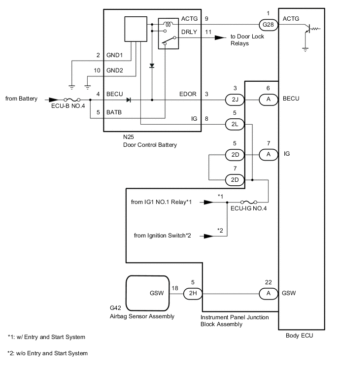
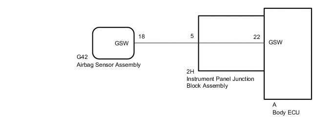
Figure 2. w/o Door Control Battery
CAUTION / NOTICE / HINT
Note
-
Inspect the fuses for circuits related to this system before performing the following procedure.
-
If the body ECU has been replaced, it is necessary to initialize the body ECU.*1
-
As the door control battery is installed between the vehicle battery and body ECU, first perform the inspections to confirm that there are no malfunctions in the power source circuit for the body ECU before performing this troubleshooting procedure.*2
-
After turning the ignition switch off, waiting time may be required before disconnecting the cable from the negative (-) battery terminal. Therefore, make sure to read the disconnecting the cable from the negative (-) battery terminal notices before proceeding with work.
-
When disconnecting the cable from the negative (-) battery terminal while performing repairs, some systems need to be initialized after the cable is reconnected.
-
If the airbag sensor assembly is replaced, refer to the Airbag System.
for Type A: Click here
for Type B: Click here
for Type C: Click here
-
*1: w/ Automatic Light Control System
-
*2: w/ Door Control Battery
PROCEDURE
-
CHECK VEHICLE TYPE
-
Check vehicle condition.
Result Result Proceed to w/ Door Control Battery A w/o Door Control Battery B
B 
GO TO STEP 8 Click here
A 
-
-
CHECK DOOR LOCK OPERATION
-
Check door lock operation.
OK All doors lock and unlock normally. Result Proceed to OK NG
NG 
GO TO PROBLEM SYMPTOMS TABLE Click here
OK
-
-
INSPECT DOOR CONTROL BATTERY
-
Remove the door control battery.
-
Inspect the door control battery.
Result Proceed to OK NG
NG
REPLACE DOOR CONTROL BATTERY Click here
OK
-
-
CHECK HARNESS AND CONNECTOR (BODY ECU - DOOR CONTROL BATTERY)
-
Disconnect the G28 body ECU connector.
-
Disconnect the N25 door control battery connector.
-
Measure the resistance according to the value(s) in the table below.
Standard Resistance Tester Connection Condition Specified Condition G28-1 (ACTG) - N25-9 (ACTG) Always Below 1 Ω G28-1 (ACTG) or N25-9 (ACTG) - Body ground Always 10 kΩ or higher Result Proceed to OK NG
NG
REPAIR OR REPLACE HARNESS OR CONNECTOR
OK
-
-
CHECK HARNESS AND CONNECTOR (DOOR CONTROL BATTERY - INSTRUMENT PANEL JUNCTION BLOCK ASSEMBLY)
-
Disconnect the N25 door control battery connector.
-
Disconnect the 2L instrument panel junction block assembly connector.
-
Measure the resistance according to the value(s) in the table below.
Standard Resistance Tester Connection Condition Specified Condition N25-8 (IG) - 2L-5 Always Below 1 Ω N25-8 (IG) or 2L-5 - Body ground Always 10 kΩ or higher Result Proceed to OK NG
NG
REPAIR OR REPLACE HARNESS OR CONNECTOR
OK
-
-
INSPECT INSTRUMENT PANEL JUNCTION BLOCK ASSEMBLY
-
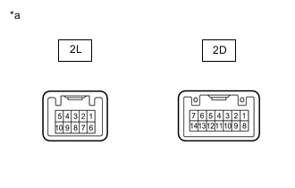
*a Component without harness connected
(Instrument Panel Junction Block Assembly)
Remove the instrument panel junction block assembly.
for LHD: Click here
for RHD: Click here
-
Remove the body ECU from the instrument panel junction block assembly.
for LHD: Click here
for RHD: Click here
-
Measure the resistance according to the value(s) in the table below.
Standard Resistance Tester Connection Condition Specified Condition 2D-7 - 2L-5 Always Below 1 Ω Result Proceed to OK NG
NG
REPLACE INSTRUMENT PANEL JUNCTION BLOCK ASSEMBLY for LHD: Click here
REPLACE INSTRUMENT PANEL JUNCTION BLOCK ASSEMBLY for RHD: Click hereOK
-
-
INSPECT DOOR CONTROL BATTERY
-
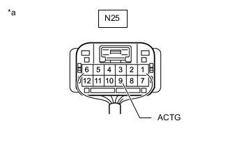
*a Rear view of wire harness connector
(to Door Control Battery)
Measure the voltage according to the value(s) in the table below.
Tech Tips
-
After the ignition switch is turned off, the door control battery is discharged in at most 30 minutes. The discharge time may be shortened depending on the amount of door control battery charge.
-
After the ignition switch is turned ON, the door control battery is charged in at most 90 minutes. The charging time may be shortened depending on the amount of door control battery charge.
Standard Voltage Tester Connection Switch Condition Specified Condition N25-9 (ACTG) - Body ground Door control battery not charged Below 2 V Door control battery charging or charged 7.3 to 9.9 V Result Proceed to OK NG -
NG
REPLACE DOOR CONTROL BATTERY Click here
OK
-
-
CHECK BODY ECU
-
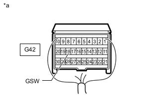
*a Rear view of wire harness connector
(to Airbag Sensor Assembly)
Disconnect the cable from the negative (-) battery terminal.
CAUTION:
Wait at least 90 seconds after disconnecting the cable from the negative (-) battery terminal to disable the SRS system.
Note
Turning the ignition switch to ON with the airbag sensor assembly connector disconnected causes other DTCs to be stored. Clear the DTCs after performing this inspection.
-
Disconnect the airbag sensor assembly connector.
for Type A: Click here
for Type B: Click here
for Type C: Click here
-
Connect the cable to the negative (-) battery terminal.
-
Measure the voltage according to the value(s) in the table below.
Standard Voltage Tester Connection Switch Condition Specified Condition G42-18 (GSW) - Body ground Ignition switch ON 2.8 to 4.3 V Result Proceed to OK NG
OK
REPLACE AIRBAG SENSOR ASSEMBLY Click here
NG
-
-
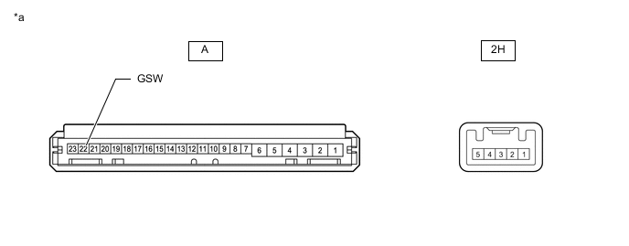
CHECK HARNESS AND CONNECTOR (INSTRUMENT PANEL JUNCTION BLOCK ASSEMBLY - AIRBAG SENSOR ASSEMBLY)
-
Disconnect the cable from the negative (-) battery terminal.
CAUTION:
Wait at least 90 seconds after disconnecting the cable from the negative (-) battery terminal to disable the SRS system.
Note
Turning the ignition switch to ON with the airbag sensor assembly connector disconnected causes other DTCs to be stored. Clear the DTCs after performing this inspection.
-
Disconnect the 2H instrument panel junction block assembly connector.
-
Disconnect the G42 airbag sensor assembly connector.
for Type A: Click here
for Type B: Click here
for Type C: Click here
-
Measure the resistance according to the value(s) in the table below.
Standard Resistance Tester Connection Condition Specified Condition 2H-5 - G42-18 (GSW) Always Below 1 Ω 2H-5 or G42-18 (GSW) - Body ground Always 10 kΩ or higher Result Proceed to OK NG
NG
REPLACE INSTRUMENT PANEL WIRE
OK
-
-
INSPECT INSTRUMENT PANEL JUNCTION BLOCK ASSEMBLY
-
Remove the instrument panel junction block assembly.
for LHD: Click here
for RHD: Click here
*a Component without harness connected
(Instrument Panel Junction Block Assembly)
- - -
Remove the body ECU from the instrument panel junction block assembly.
for LHD: Click here
for RHD: Click here
-
Measure the resistance according to the value(s) in the table below.
Standard Resistance Tester Connection Condition Specified Condition A-22 (GSW) - 2H-5 Always Below 1 Ω Result Proceed to OK NG
OK
REPLACE BODY ECU for LHD: Click here
REPLACE BODY ECU for RHD: Click hereNG
REPLACE INSTRUMENT PANEL JUNCTION BLOCK ASSEMBLY for LHD: Click here
REPLACE INSTRUMENT PANEL JUNCTION BLOCK ASSEMBLY for RHD: Click here -