POWER DOOR LOCK CONTROL SYSTEM All Doors LOCK/UNLOCK Functions do not Operate Via Door Control Switch or Door Key Cylinder
DESCRIPTION
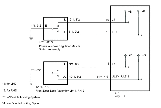
The body ECU receives switch signals from the power window regulator master switch assembly and driver door key cylinder lock or unlock switch signals from the front door lock assembly LH*1 or RH*2. The body ECU activates the door lock motor on each door according to these signals.
-
*1: for LHD
-
*2: for RHD
WIRING DIAGRAM
-
Figure 1. w/ Entry and Start System
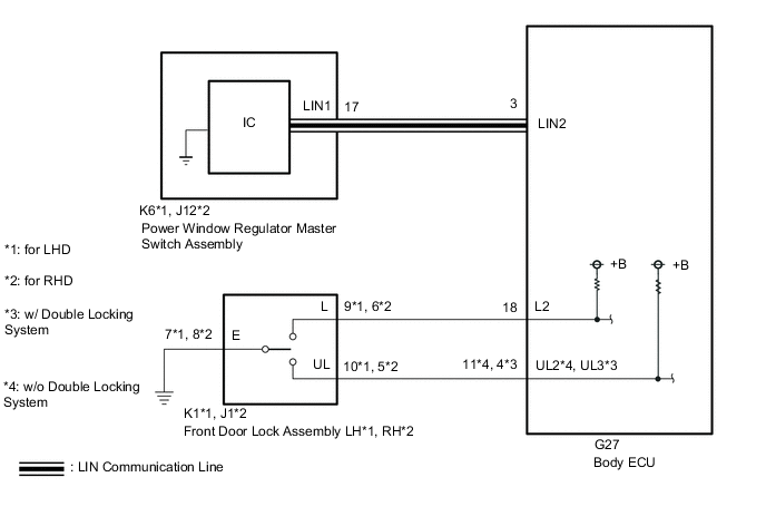
Figure 2. w/o Entry and Start System
CAUTION / NOTICE / HINT
Note
-
If the body ECU has been replaced, it is necessary to initialize the body ECU.*1
-
As the door control battery is installed between the vehicle battery and body ECU, first perform the inspections to confirm that there are no malfunctions in the power source circuit for the body ECU before performing this troubleshooting procedure.*2
-
*1: w/ Automatic Light Control System
-
*2: w/ Door Control Battery
PROCEDURE
-
CHECK DOOR LOCK OPERATION
-
Check door lock operation.
Result Result Proceed to All doors cannot be locked by power window regulator master switch assembly (w/ Entry and Start System) A All doors cannot be locked by power window regulator master switch assembly (w/o Entry and Start System) B All doors cannot be locked by driver door key cylinder C
B 
INSPECT POWER WINDOW REGULATOR MASTER SWITCH ASSEMBLY Click here
C
INSPECT FRONT DOOR LOCK ASSEMBLY Click here
A 
-
-
CHECK POWER WINDOW CONTROL SYSTEM
-
Check the power window control system.
OK Power window control system operates normally. Result Proceed to OK NG
NG 
GO TO POWER WINDOW CONTROL SYSTEM Click here
OK
-
-
REPLACE POWER WINDOW REGULATOR MASTER SWITCH ASSEMBLY
-
Replace the power window regulator master switch assembly.
Result Proceed to NEXT
NEXT
-
-
CHECK DOOR LOCK OPERATION
-
Check door lock operation.
OK Power door lock control system operates normally. Result Proceed to OK NG
OK
END (POWER WINDOW REGULATOR MASTER SWITCH ASSEMBLY WAS DEFECTIVE)
NG
REPLACE BODY ECU for LHD: Click here
REPLACE BODY ECU for RHD: Click here -
-
INSPECT POWER WINDOW REGULATOR MASTER SWITCH ASSEMBLY
-
Remove the power window regulator master switch assembly.
-
Inspect the power window regulator master switch assembly.
Result Proceed to OK NG
NG
REPLACE POWER WINDOW REGULATOR MASTER SWITCH ASSEMBLY Click here
OK
-
-
CHECK HARNESS AND CONNECTOR (POWER WINDOW REGULATOR MASTER SWITCH ASSEMBLY - BODY ECU AND BODY GROUND)
-
*1: for LHD
-
*2: for RHD
-
Disconnect the K5*1 or J11*2 power window regulator master switch assembly connector.
-
Disconnect the G27 body ECU connector.
-
Measure the resistance according to the value(s) in the table below.
Standard Resistance for LHD Tester Connection Condition Specified Condition K5-2 (L) - G27-19 (L1) Always Below 1 Ω K5-2 (L) or G27-19 (L1) - Body ground Always 10 kΩ or higher K5-8 (UL) - G27-12 (UL1) Always Below 1 Ω K5-8 (UL) or G27-12 (UL1) - Body ground Always 10 kΩ or higher K5-1 (E) - Body ground Always Below 1 Ω for RHD Tester Connection Condition Specified Condition J11-8 (L) - G27-19 (L1) Always Below 1 Ω J11-8 (L) or G27-19 (L1) - Body ground Always 10 kΩ or higher J11-2 (UL) - G27-12 (UL1) Always Below 1 Ω J11-2 (UL) or G27-12 (UL1) - Body ground Always 10 kΩ or higher J11-9 (E) - Body ground Always Below 1 Ω Result Proceed to OK NG
OK
REPLACE BODY ECU for LHD: Click here
REPLACE BODY ECU for RHD: Click hereNG
REPAIR OR REPLACE HARNESS OR CONNECTOR
-
-
INSPECT FRONT DOOR LOCK ASSEMBLY
-
*1: for LHD
-
*2: for RHD
-
Remove the front door lock assembly LH*1 or RH*2.
-
Inspect the front door lock assembly LH*1 or RH*2.
Result Proceed to OK NG
NG
REPLACE FRONT DOOR LOCK ASSEMBLY Click here
OK
-
-
CHECK HARNESS AND CONNECTOR (FRONT DOOR LOCK ASSEMBLY - BODY ECU AND BODY GROUND)
-
*1: for LHD
-
*2: for RHD
-
Disconnect the K1*1 or J1*2 front door lock assembly LH*1 or RH*2 connector.
-
Disconnect the G27 body ECU connector.
-
Measure the resistance according to the value(s) in the table below.
Standard Resistance for LHD Tester Connection Condition Specified Condition K1-9 (L) - G27-18 (L2) Always Below 1 Ω K1-9 (L) or G27-18 (L2) - Body ground Always 10 kΩ or higher K1-10 (UL) - G27-11 (UL2) Always Below 1 Ω K1-10 (UL) or G27-11 (UL2) - Body ground Always 10 kΩ or higher K1-7 (E) - Body ground Always Below 1 Ω for RHD, w/o Double Locking System Tester Connection Condition Specified Condition J1-6 (L) - G27-18 (L2) Always Below 1 Ω J1-6 (L) or G27-18 (L2) - Body ground Always 10 kΩ or higher J1-5 (UL) - G27-11 (UL2) Always Below 1 Ω J1-5 (UL) or G27-11 (UL2) - Body ground Always 10 kΩ or higher J1-8 (E) - Body ground Always Below 1 Ω for RHD, w/ Double Locking System Tester Connection Condition Specified Condition J1-6 (L) - G27-18 (L2) Always Below 1 Ω J1-6 (L) or G27-18 (L2) - Body ground Always 10 kΩ or higher J1-5 (UL) - G27-4 (UL3) Always Below 1 Ω J1-5 (UL) or G27-4 (UL3) - Body ground Always 10 kΩ or higher J1-8 (E) - Body ground Always Below 1 Ω Result Proceed to OK NG
OK
REPLACE BODY ECU for LHD: Click here
REPLACE BODY ECU for RHD: Click hereNG
REPAIR OR REPLACE HARNESS OR CONNECTOR
-