CAN COMMUNICATION SYSTEM(for LHD without Central Gateway ECU) Short to B+ in CAN Bus Line
DESCRIPTION
There may be a short circuit between the CAN bus lines and +B when the resistance between terminals 6 (CANH) and 16 (BAT) or terminals 14 (CANL) and 16 (BAT) of the DLC3 is below 6 kΩ.
| Symptom | Trouble Area |
|---|---|
| The resistance between terminals 6 (CANH) and 16 (BAT) or terminals 14 (CANL) and 16 (BAT) of the DLC3 is below 6 kΩ. |
|
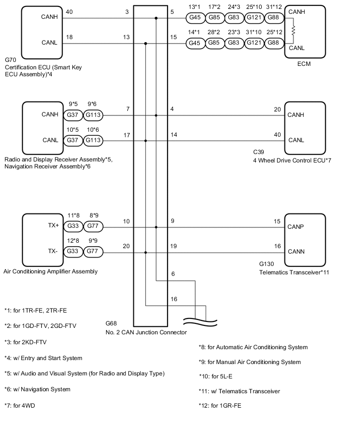
*2: for Automatic Air Conditioning System or for Manual Air Conditioning System
*3: w/ Entry and Start System
*4: for 4WD
*5: w/ Audio and Visual System (for Radio and Display Type)
*6: w/ Navigation System
*7: for LED Headlight or w/ Headlight Cleaner System
*8: w/ Airbag System
*9: w/ Stop and Start System
*10: w/ Telematics Transceiver
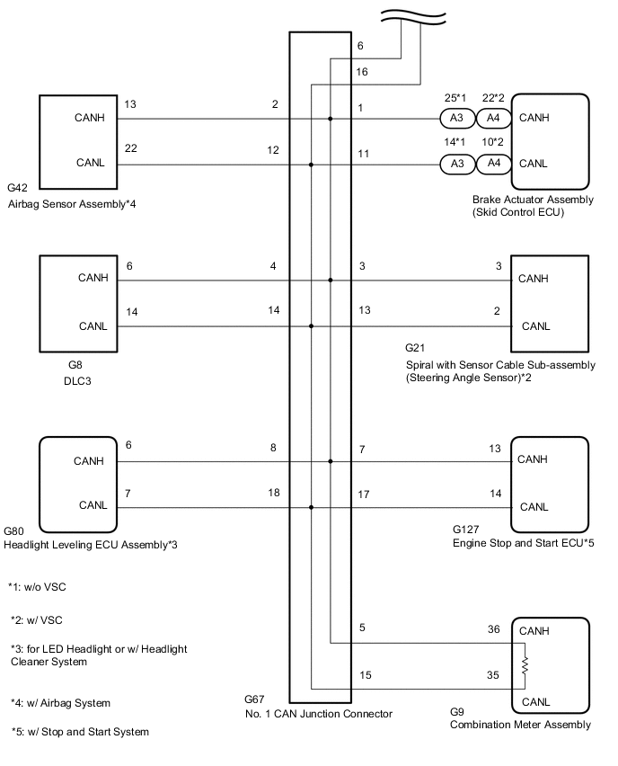
WIRING DIAGRAM
CAUTION / NOTICE / HINT
Note
-
Because the order of diagnosis is important to allow correct diagnosis, make sure to begin troubleshooting using How to Proceed with Troubleshooting when CAN communication system related DTCs are output.
-
Before measuring the resistance of the CAN bus, turn the ignition switch off and leave the vehicle for 1 minute or more without operating the key, switches or opening or closing the doors. After that, disconnect the cable from the negative (-) battery terminal and leave the vehicle for 1 minute or more before measuring the resistance.
-
After turning the ignition switch off, waiting time may be required before disconnecting the cable from the battery terminal. Therefore, make sure to read the disconnecting the cable from the battery terminal notice before proceeding with work.
-
The vehicle is equipped with an SRS (Supplemental Restraint System) which includes components such as airbags. Before servicing (including removal or installation of parts), be sure to read the Precaution in the SRS.
Type A:
Type B:
Type C:
-
When replacing the combination meter assembly, make sure to replace it with a new one.
-
Before replacing the certification ECU (smart key ECU assembly), refer to the service bulletin.
Tech Tips
-
Operating the ignition switch, any switches or any doors triggers related ECU and sensor communication with the CAN, which causes resistance variation.
-
Even after DTCs are cleared, if a DTC is stored again after driving the vehicle for a while, the malfunction may be occurring due to vibration of the vehicle. In such a case, wiggling the ECUs or wire harness while performing the inspection below may help determine the cause of the malfunction.
-
Connectors that connect to the CAN junction connector can be distinguished by the color of their CAN bus lines. When the connectors have been disconnected from the CAN junction connector, reconnecting the connectors to non-original positions on the CAN junction connector does not affect system performance. However, it is preferred to reconnect the connectors to their original positions to avoid negative effects on the wiring such as tension on the wiring harnesses, and to make future maintenance easier.
-
When replacing the navigation receiver assembly, it is necessary to perform the vehicle contract setting for Connected Services.
PROCEDURE
-
CHECK FOR SHORT TO B+ IN CAN BUS WIRE (DLC3 CAN BRANCH WIRE)
-
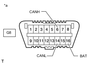
*a Front view of DLC3 Disconnect the cable from the negative (-) battery terminal.
-
Disconnect the No. 1 CAN junction connector.
-
Measure the resistance according to the value(s) in the table below.
Standard Resistance Tester Connection Condition Specified Condition G8-6 (CANH) - G8-16 (BAT) Cable disconnected from negative (-) battery terminal 6 kΩ or higher G8-14 (CANL) - G8-16 (BAT) Cable disconnected from negative (-) battery terminal 6 kΩ or higher Result Proceed to OK NG
NG 
REPAIR OR REPLACE CAN BRANCH WIRE CONNECTED TO DLC3 (CANH, CANL)
OK 
-
-
CONNECT CONNECTOR
-
Reconnect the No. 1 CAN junction connector.
Result Proceed to NEXT
NEXT
-
-
CHECK FOR SHORT TO B+ IN CAN BUS WIRE (NO. 2 CAN JUNCTION CONNECTOR SIDE)
-
*a Front view of DLC3 Disconnect the No. 2 CAN junction connector.
-
Measure the resistance according to the value(s) in the table below.
Standard Resistance Tester Connection Condition Specified Condition G8-6 (CANH) - G8-16 (BAT) Cable disconnected from negative (-) battery terminal 6 kΩ or higher G8-14 (CANL) - G8-16 (BAT) Cable disconnected from negative (-) battery terminal 6 kΩ or higher Result Proceed to OK NG
NG 
CONNECT CONNECTOR Click here
OK
-
-
CHECK FOR SHORT TO B+ IN CAN BUS WIRE (NO. 2 CAN JUNCTION CONNECTOR)
-
Measure the resistance according to the value(s) in the table below.
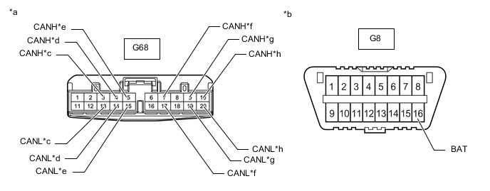
*a Front view of wire harness connector
(to No. 2 CAN Junction Connector)
*b Front view of DLC3 *c to Certification ECU (Smart Key ECU Assembly) (w/ Entry and Start System) *d to 4 Wheel Drive Control ECU (for 4WD) *e to ECM *f
-
to Radio and Display Receiver Assembly (w/ Audio and Visual System [for Radio and Display Type])
-
to Navigation Receiver Assembly (w/ Navigation System)
*g to Telematics Transceiver (w/ Telematics Transceiver) *h
-
to Air Conditioning Amplifier Assembly (for Automatic Air Conditioning System)
-
to Air Conditioning Amplifier Assembly (for Manual Air Conditioning System)
Standard Resistance *1: w/ Entry and Start SystemTester Connection Condition Specified Condition Connected to G68-3 (CANH) - G8-16 (BAT) Cable disconnected from negative (-) battery terminal 6 kΩ or higher Certification ECU (Smart Key ECU Assembly)*1 G68-13 (CANL) - G8-16 (BAT) Cable disconnected from negative (-) battery terminal 6 kΩ or higher G68-4 (CANH) - G8-16 (BAT) Cable disconnected from negative (-) battery terminal 6 kΩ or higher 4 Wheel Drive Control ECU*2 G68-14 (CANL) - G8-16 (BAT) Cable disconnected from negative (-) battery terminal 6 kΩ or higher G68-5 (CANH) - G8-16 (BAT) Cable disconnected from negative (-) battery terminal 6 kΩ or higher ECM G68-15 (CANL) - G8-16 (BAT) Cable disconnected from negative (-) battery terminal 6 kΩ or higher G68-7 (CANH) - G8-16 (BAT) Cable disconnected from negative (-) battery terminal 6 kΩ or higher
-
Radio and Display Receiver Assembly*3
-
Navigation Receiver Assembly*4
G68-17 (CANL) - G8-16 (BAT) Cable disconnected from negative (-) battery terminal 6 kΩ or higher G68-9 (CANH) - G8-16 (BAT) Cable disconnected from negative (-) battery terminal 6 kΩ or higher Telematics Transceiver*7 G68-19 (CANL) - G8-16 (BAT) Cable disconnected from negative (-) battery terminal 6 kΩ or higher G68-10 (CANH) - G8-16 (BAT) Cable disconnected from negative (-) battery terminal 6 kΩ or higher Air Conditioning Amplifier Assembly*5, *6 G68-20 (CANL) - G8-16 (BAT) Cable disconnected from negative (-) battery terminal 6 kΩ or higher
*2: for 4WD
*3: w/ Audio and Visual System (for Radio and Display Type)
*4: w/ Navigation System
*5: for Automatic Air Conditioning System
*6: for Manual Air Conditioning System
*7: w/ Telematics Transceiver
Result Result Proceed to OK A NG (to certification ECU [smart key ECU assembly] CAN branch wire) (w/ Entry and Start System) B NG (to 4 wheel drive control ECU CAN branch wire) (for 4WD) C NG (to ECM CAN main wire) (for 1TR-FE, 2TR-FE) D NG (to ECM CAN main wire) (for 2KD-FTV) E NG (to ECM CAN main wire) (for 1GD-FTV, 2GD-FTV) F NG (to ECM CAN main wire) (for 5L-E) G NG (to ECM CAN main wire) (for 1GR-FE) H NG (to radio and display receiver assembly CAN branch wire) (w/ Audio and Visual System [for Radio and Display Type]) I NG (to navigation receiver assembly CAN branch wire) (w/ Navigation System) J NG (to telematics transceiver CAN branch wire) (w/ Telematics Transceiver) K NG (to air conditioning amplifier assembly CAN branch wire) (for Automatic Air Conditioning System) L NG (to air conditioning amplifier assembly CAN branch wire) (for Manual Air Conditioning System) M -
A
REPLACE NO. 2 CAN JUNCTION CONNECTOR
C
CONNECT CONNECTOR Click here
D
CONNECT CONNECTOR Click here
E
CONNECT CONNECTOR Click here
F
CONNECT CONNECTOR Click here
G
CONNECT CONNECTOR Click here
H
CONNECT CONNECTOR Click here
I
CONNECT CONNECTOR Click here
J
CONNECT CONNECTOR Click here
K
CONNECT CONNECTOR Click here
L
CONNECT CONNECTOR Click here
M
CONNECT CONNECTOR Click here
B
-
-
CONNECT CONNECTOR
-
Reconnect the No. 2 CAN junction connector.
Result Proceed to NEXT
NEXT
-
-
CHECK FOR SHORT TO B+ IN CAN BUS WIRE (CERTIFICATION ECU BRANCH WIRE)
-
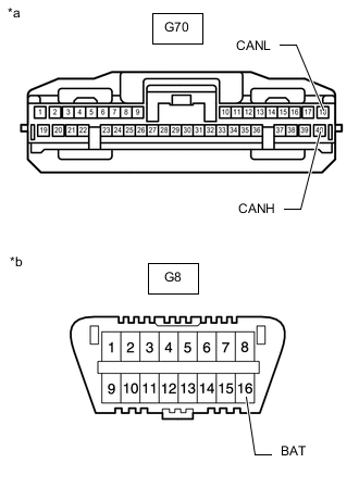
*a Front view of wire harness connector
(to Certification ECU [Smart Key ECU Assembly])
*b Front view of DLC3 Disconnect the certification ECU (smart key ECU assembly) connector.
-
Measure the resistance according to the value(s) in the table below.
Standard Resistance Tester Connection Condition Specified Condition G70-40 (CANH) - G8-16 (BAT) Cable disconnected from negative (-) battery terminal 6 kΩ or higher G70-18 (CANL) - G8-16 (BAT) Cable disconnected from negative (-) battery terminal 6 kΩ or higher Result Proceed to OK NG
OK
REPLACE CERTIFICATION ECU (SMART KEY ECU ASSEMBLY)
NG
REPAIR OR REPLACE CAN BRANCH WIRE CONNECTED TO CERTIFICATION ECU (CANH, CANL)
-
-
CONNECT CONNECTOR
-
Reconnect the No. 2 CAN junction connector.
Result Proceed to NEXT
NEXT
-
-
CHECK FOR SHORT TO B+ IN CAN BUS WIRE (4 WHEEL DRIVE CONTROL ECU BRANCH WIRE)
-
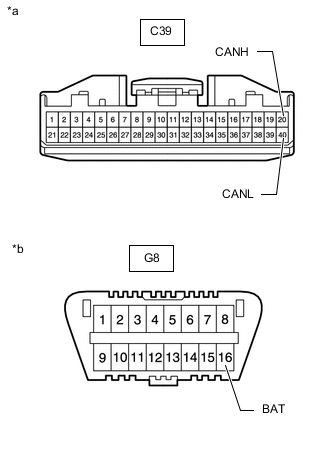
*a Front view of wire harness connector
(to 4 Wheel Drive Control ECU)
*b Front view of DLC3 Disconnect the 4 wheel drive control ECU connector.
-
Measure the resistance according to the value(s) in the table below.
Standard Resistance Tester Connection Condition Specified Condition C39-20 (CANH) - G8-16 (BAT) Cable disconnected from negative (-) battery terminal 6 kΩ or higher C39-40 (CANL) - G8-16 (BAT) Cable disconnected from negative (-) battery terminal 6 kΩ or higher Result Proceed to OK NG
OK
REPLACE 4 WHEEL DRIVE CONTROL ECU Click here
NG
REPAIR OR REPLACE CAN BRANCH WIRE CONNECTED TO 4 WHEEL DRIVE CONTROL ECU (CANH, CANL)
-
-
CONNECT CONNECTOR
-
Reconnect the No. 2 CAN junction connector.
Result Proceed to NEXT
NEXT
-
-
CHECK FOR SHORT TO B+ IN CAN BUS WIRE (ECM)
-
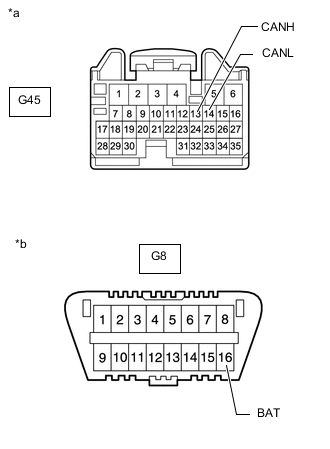
*a Front view of wire harness connector
(to ECM)
*b Front view of DLC3 Disconnect the ECM connector.
-
Measure the resistance according to the value(s) in the table below.
Standard Resistance Tester Connection Condition Specified Condition G45-13 (CANH) - G8-16 (BAT) Cable disconnected from negative (-) battery terminal 6 kΩ or higher G45-14 (CANL) - G8-16 (BAT) Cable disconnected from negative (-) battery terminal 6 kΩ or higher Result Proceed to OK NG
OK
REPLACE ECM for 1TR-FE: REPLACE ECM Click here
REPLACE ECM for 2TR-FE: REPLACE ECM Click hereNG
REPAIR OR REPLACE CAN MAIN WIRE CONNECTED TO ECM (CANH, CANL)
-
-
CONNECT CONNECTOR
-
Reconnect the No. 2 CAN junction connector.
Result Proceed to NEXT
NEXT
-
-
CHECK FOR SHORT TO B+ IN CAN BUS WIRE (ECM)
-
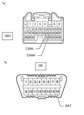
*a Front view of wire harness connector
(to ECM)
*b Front view of DLC3 Disconnect the ECM connector.
-
Measure the resistance according to the value(s) in the table below.
Standard Resistance Tester Connection Condition Specified Condition G83-24 (CANH) - G8-16 (BAT) Cable disconnected from negative (-) battery terminal 6 kΩ or higher G83-23 (CANL) - G8-16 (BAT) Cable disconnected from negative (-) battery terminal 6 kΩ or higher Result Proceed to OK NG
OK
REPLACE ECM Click here
NG
REPAIR OR REPLACE CAN MAIN WIRE CONNECTED TO ECM (CANH, CANL)
-
-
CONNECT CONNECTOR
-
Reconnect the No. 2 CAN junction connector.
Result Proceed to NEXT
NEXT
-
-
CHECK FOR SHORT TO B+ IN CAN BUS WIRE (ECM)
-
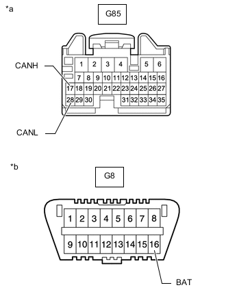
*a Front view of wire harness connector
(to ECM)
*b Front view of DLC3 Disconnect the ECM connector.
-
Measure the resistance according to the value(s) in the table below.
Standard Resistance Tester Connection Condition Specified Condition G85-17 (CANH) - G8-16 (BAT) Cable disconnected from negative (-) battery terminal 6 kΩ or higher G85-28 (CANL) - G8-16 (BAT) Cable disconnected from negative (-) battery terminal 6 kΩ or higher Result Proceed to OK NG
OK
REPLACE ECM for 1GD-FTV: REPLACE ECM Click here
REPLACE ECM for 2GD-FTV: REPLACE ECM Click hereNG
REPAIR OR REPLACE CAN MAIN WIRE CONNECTED TO ECM (CANH, CANL)
-
-
CONNECT CONNECTOR
-
Reconnect the No. 2 CAN junction connector.
Result Proceed to NEXT
NEXT
-
-
CHECK FOR SHORT TO B+ IN CAN BUS WIRE (ECM)
-
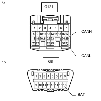
*a Front view of wire harness connector
(to ECM)
*b Front view of DLC3 Disconnect the ECM connector.
-
Measure the resistance according to the value(s) in the table below.
Standard Resistance Tester Connection Condition Specified Condition G121-25 (CANH) - G8-16 (BAT) Cable disconnected from negative (-) battery terminal 6 kΩ or higher G121-31 (CANL) - G8-16 (BAT) Cable disconnected from negative (-) battery terminal 6 kΩ or higher Result Proceed to OK NG
OK
REPLACE ECM Click here
NG
REPAIR OR REPLACE CAN MAIN WIRE CONNECTED TO ECM (CANH, CANL)
-
-
CONNECT CONNECTOR
-
Reconnect the No. 2 CAN junction connector.
Result Proceed to NEXT
NEXT
-
-
CHECK FOR SHORT TO B+ IN CAN BUS WIRE (ECM)
-
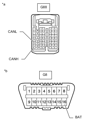
*a Front view of wire harness connector
(to ECM)
*b Front view of DLC3 Disconnect the ECM connector.
-
Measure the resistance according to the value(s) in the table below.
Standard Resistance Tester Connection Condition Specified Condition G88-31 (CANH) - G8-16 (BAT) Cable disconnected from negative (-) battery terminal 6 kΩ or higher G88-25 (CANL) - G8-16 (BAT) Cable disconnected from negative (-) battery terminal 6 kΩ or higher Result Proceed to OK NG
OK
REPLACE ECM Click here
NG
REPAIR OR REPLACE CAN MAIN WIRE CONNECTED TO ECM (CANH, CANL)
-
-
CONNECT CONNECTOR
-
Reconnect the No. 2 CAN junction connector.
Result Proceed to NEXT
NEXT
-
-
CHECK FOR SHORT TO B+ IN CAN BUS WIRE (RADIO AND DISPLAY RECEIVER ASSEMBLY BRANCH WIRE)
-
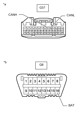
*a Front view of wire harness connector
(to Radio and Display Receiver Assembly)
*b Front view of DLC3 Disconnect the radio and display receiver assembly connector.
-
Measure the resistance according to the value(s) in the table below.
Standard Resistance Tester Connection Condition Specified Condition G37-9 (CANH) - G8-16 (BAT) Cable disconnected from negative (-) battery terminal 6 kΩ or higher G37-10 (CANL) - G8-16 (BAT) Cable disconnected from negative (-) battery terminal 6 kΩ or higher Result Proceed to OK NG
OK
REPLACE RADIO AND DISPLAY RECEIVER ASSEMBLY Click here
NG
REPAIR OR REPLACE CAN BRANCH WIRE CONNECTED TO RADIO AND DISPLAY RECEIVER ASSEMBLY (CANH, CANL)
-
-
CONNECT CONNECTOR
-
Reconnect the No. 2 CAN junction connector.
Result Proceed to NEXT
NEXT
-
-
CHECK FOR SHORT TO B+ IN CAN BUS WIRE (NAVIGATION RECEIVER ASSEMBLY BRANCH WIRE)
-

*a Front view of wire harness connector
(to Navigation Receiver Assembly)
*b Front view of DLC3 Disconnect the navigation receiver assembly connector.
-
Measure the resistance according to the value(s) in the table below.
Standard Resistance Tester Connection Condition Specified Condition G113-9 (CANH) - G8-16 (BAT) Cable disconnected from negative (-) battery terminal 6 kΩ or higher G113-10 (CANL) - G8-16 (BAT) Cable disconnected from negative (-) battery terminal 6 kΩ or higher Result Proceed to OK NG
OK
REPLACE NAVIGATION RECEIVER ASSEMBLY Click here
NG
REPAIR OR REPLACE CAN BRANCH WIRE CONNECTED TO NAVIGATION RECEIVER ASSEMBLY (CANH, CANL)
-
-
CONNECT CONNECTOR
-
Reconnect the No. 2 CAN junction connector.
Result Proceed to NEXT
NEXT
-
-
CHECK FOR SHORT TO B+ IN CAN BUS WIRE (TELEMATICS TRANSCEIVER BRANCH WIRE)
-
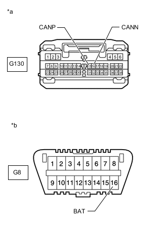
*a Front view of wire harness connector
(to Telematics Transceiver)
*b Front view of DLC3 Disconnect the telematics transceiver connector.
-
Measure the resistance according to the value(s) in the table below.
Standard Resistance Tester Connection Condition Specified Condition G130-15 (CANP) - G8-16 (BAT) Cable disconnected from negative (-) battery terminal 6 kΩ or higher G130-16 (CANN) - G8-16 (BAT) Cable disconnected from negative (-) battery terminal 6 kΩ or higher Result Proceed to OK NG
OK
REPLACE TELEMATICS TRANSCEIVER Click here
NG
REPAIR OR REPLACE CAN BRANCH WIRE CONNECTED TO TELEMATICS TRANSCEIVER (CANP, CANN)
-
-
CONNECT CONNECTOR
-
Reconnect the No. 2 CAN junction connector.
Result Proceed to NEXT
NEXT
-
-
CHECK FOR SHORT TO B+ IN CAN BUS WIRE (AIR CONDITIONING AMPLIFIER ASSEMBLY BRANCH WIRE)
-
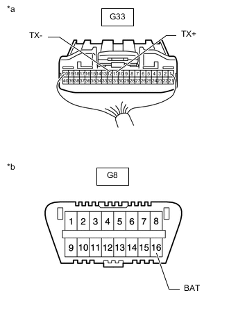
*a Rear view of wire harness connector
(to Air Conditioning Amplifier Assembly)
*b Front view of DLC3 Disconnect the air conditioning amplifier assembly connector.
-
Measure the resistance according to the value(s) in the table below.
Standard Resistance Tester Connection Condition Specified Condition G33-11 (TX+) - G8-16 (BAT) Cable disconnected from negative (-) battery terminal 6 kΩ or higher G33-12 (TX-) - G8-16 (BAT) Cable disconnected from negative (-) battery terminal 6 kΩ or higher Result Proceed to OK NG
OK
REPLACE AIR CONDITIONING AMPLIFIER ASSEMBLY Click here
NG
REPAIR OR REPLACE CAN BRANCH WIRE CONNECTED TO AIR CONDITIONING AMPLIFIER ASSEMBLY (TX+, TX-)
-
-
CONNECT CONNECTOR
-
Reconnect the No. 2 CAN junction connector.
Result Proceed to NEXT
NEXT
-
-
CHECK FOR SHORT TO B+ IN CAN BUS WIRE (AIR CONDITIONING AMPLIFIER ASSEMBLY BRANCH WIRE)
-
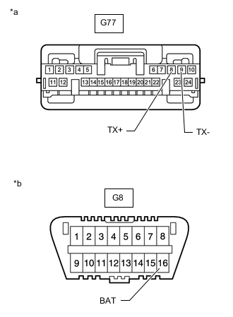
*a Front view of wire harness connector
(to Air Conditioning Amplifier Assembly)
*b Front view of DLC3 Disconnect the air conditioning amplifier assembly connector.
-
Measure the resistance according to the value(s) in the table below.
Standard Resistance Tester Connection Condition Specified Condition G77-8 (TX+) - G8-16 (BAT) Cable disconnected from negative (-) battery terminal 6 kΩ or higher G77-9 (TX-) - G8-16 (BAT) Cable disconnected from negative (-) battery terminal 6 kΩ or higher Result Proceed to OK NG
OK
REPLACE AIR CONDITIONING AMPLIFIER ASSEMBLY Click here
NG
REPAIR OR REPLACE CAN BRANCH WIRE CONNECTED TO AIR CONDITIONING AMPLIFIER ASSEMBLY (TX+, TX-)
-
-
CONNECT CONNECTOR
-
Reconnect the No. 2 CAN junction connector.
Result Proceed to NEXT
NEXT
-
-
CHECK SHORT TO B+ IN CAN BUS WIRE (NO. 1 CAN JUNCTION CONNECTOR)
-
Disconnect the No. 1 CAN junction connector.
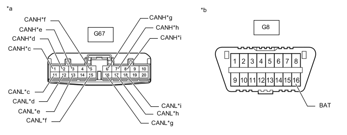
*a Front view of wire harness connector
(to No. 1 CAN Junction Connector)
*b Front view of DLC3 *c to Brake Actuator Assembly (Skid Control ECU) *d to Airbag Sensor Assembly (w/ Airbag System) *e to Spiral with Sensor Cable Sub-assembly (Steering Angle Sensor) (w/ VSC) *f to Combination Meter Assembly *g to No. 2 CAN Junction Connector *h to Engine Stop and Start ECU (w/ Stop and Start System) *i to Headlight Leveling ECU Assembly (for LED Headlight or w/ Headlight Cleaner System) - - -
Measure the resistance according to the value(s) in the table below.
Standard Resistance *1: w/ VSCTester Connection Condition Specified Condition Connected to G67-1 (CANH) - G8-16 (BAT) Cable disconnected from negative (-) battery terminal 6 kΩ or higher Brake Actuator Assembly (Skid Control ECU) G67-11 (CANL) - G8-16 (BAT) Cable disconnected from negative (-) battery terminal 6 kΩ or higher G67-2 (CANH) - G8-16 (BAT) Cable disconnected from negative (-) battery terminal 6 kΩ or higher Airbag Sensor Assembly*3 G67-12 (CANL) - G8-16 (BAT) Cable disconnected from negative (-) battery terminal 6 kΩ or higher G67-3 (CANH) - G8-16 (BAT) Cable disconnected from negative (-) battery terminal 6 kΩ or higher Spiral with Sensor Cable Sub-assembly (Steering Angle Sensor)*1 G67-13 (CANL) - G8-16 (BAT) Cable disconnected from negative (-) battery terminal 6 kΩ or higher G67-5 (CANH) - G8-16 (BAT) Cable disconnected from negative (-) battery terminal 6 kΩ or higher Combination Meter Assembly G67-15 (CANL) - G8-16 (BAT) Cable disconnected from negative (-) battery terminal 6 kΩ or higher G67-6 (CANH) - G8-16 (BAT) Cable disconnected from negative (-) battery terminal 6 kΩ or higher No. 2 CAN Junction Connector G67-16 (CANL) - G8-16 (BAT) Cable disconnected from negative (-) battery terminal 6 kΩ or higher G67-7 (CANH) - G8-16 (BAT) Cable disconnected from negative (-) battery terminal 6 kΩ or higher Engine Stop and Start ECU*4 G67-17 (CANL) - G8-16 (BAT) Cable disconnected from negative (-) battery terminal 6 kΩ or higher G67-8 (CANH) - G8-16 (BAT) Cable disconnected from negative (-) battery terminal 6 kΩ or higher Headlight Leveling ECU Assembly*2 G67-18 (CANL) - G8-16 (BAT) Cable disconnected from negative (-) battery terminal 6 kΩ or higher
*2: for LED Headlight or w/ Headlight Cleaner System
*3: w/ Airbag System
*4: w/ Stop and Start System
Result Result Proceed to OK A NG (to brake actuator assembly [skid Control ECU] CAN branch wire) B NG (to airbag sensor assembly CAN branch wire) (w/ Airbag System) C NG (to spiral with sensor cable sub-assembly [steering angle sensor] CAN branch wire) (w/ VSC) D NG (to combination meter assembly CAN main wire) E NG (to engine stop and start ECU CAN branch wire) (w/ Stop and Start System) F NG (to headlight leveling ECU assembly CAN branch wire) (for LED Headlight or w/ Headlight Cleaner System) G NG (to No. 2 CAN junction connector CAN main wire) H
A
REPLACE NO. 1 CAN JUNCTION CONNECTOR
C
CONNECT CONNECTOR Click here
D
CONNECT CONNECTOR Click here
E
CONNECT CONNECTOR Click here
F
CONNECT CONNECTOR Click here
G
CONNECT CONNECTOR Click here
H
REPAIR OR REPLACE CAN MAIN WIRE OR CONNECTOR (NO. 1 CAN JUNCTION CONNECTOR - NO. 2 CAN JUNCTION CONNECTOR)
B
-
-
CONNECT CONNECTOR
-
Reconnect the No. 1 CAN junction connector.
Result Proceed to NEXT
NEXT
-
-
CHECK FOR SHORT TO B+ IN CAN BUS WIRE (SKID CONTROL ECU BRANCH WIRE)
-
Disconnect the brake actuator assembly (skid control ECU) connector.
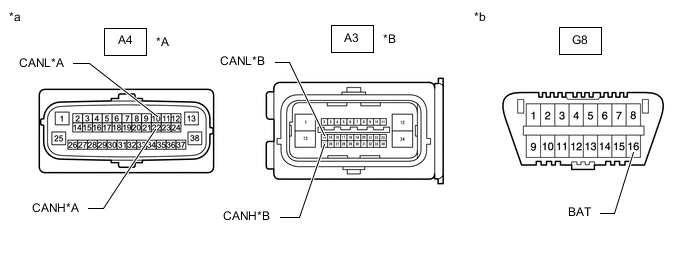
*A w/ VSC *B w/o VSC *a Front view of wire harness connector
(to Brake Actuator Assembly [Skid Control ECU])
*b Front view of DLC3 -
Measure the resistance according to the value(s) in the table below.
Standard Resistance w/ VSC Tester Connection Condition Specified Condition A4-22 (CANH) - G8-16 (BAT) Cable disconnected from negative (-) battery terminal 6 kΩ or higher A4-10 (CANL) - G8-16 (BAT) Cable disconnected from negative (-) battery terminal 6 kΩ or higher w/o VSC Tester Connection Condition Specified Condition A3-25 (CANH) - G8-16 (BAT) Cable disconnected from negative (-) battery terminal 6 kΩ or higher A3-14 (CANL) - G8-16 (BAT) Cable disconnected from negative (-) battery terminal 6 kΩ or higher Result Proceed to OK NG
OK
REPLACE BRAKE ACTUATOR ASSEMBLY w/ VSC: REPLACE BRAKE ACTUATOR ASSEMBLY Click here
REPLACE BRAKE ACTUATOR ASSEMBLY w/o VSC: REPLACE BRAKE ACTUATOR ASSEMBLY Click hereNG
REPAIR OR REPLACE CAN BRANCH WIRE CONNECTED TO SKID CONTROL ECU (CANH, CANL)
-
-
CONNECT CONNECTOR
-
Reconnect the No. 1 CAN junction connector.
Result Proceed to NEXT
NEXT
-
-
CHECK FOR SHORT TO B+ IN CAN BUS WIRE (AIRBAG SENSOR ASSEMBLY BRANCH WIRE)
-
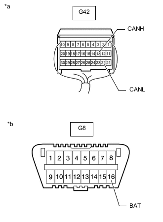
*a Rear view of wire harness connector
(to Airbag sensor Assembly)
*b Front view of DLC3 Disconnect the airbag sensor assembly connector.
Type A:
Type B:
Type C:
-
Measure the resistance according to the value(s) in the table below.
Standard Resistance Tester Connection Condition Specified Condition G42-13 (CANH) - G8-16 (BAT) Cable disconnected from negative (-) battery terminal 6 kΩ or higher G42-22 (CANL) - G8-16 (BAT) Cable disconnected from negative (-) battery terminal 6 kΩ or higher Result Proceed to OK NG
OK
REPLACE AIRBAG SENSOR ASSEMBLY Click here
NG
REPAIR OR REPLACE CAN BRANCH WIRE CONNECTED TO AIRBAG SENSOR ASSEMBLY (CANH, CANL)
-
-
CONNECT CONNECTOR
-
Reconnect the No. 1 CAN junction connector.
Result Proceed to NEXT
NEXT
-
-
CHECK FOR SHORT TO B+ IN CAN BUS WIRE (STEERING ANGLE SENSOR BRANCH WIRE)
-
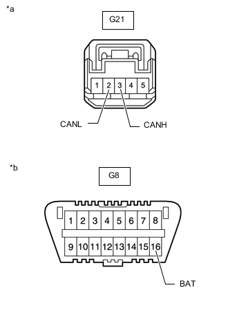
*a Front view of wire harness connector
(to Spiral with Sensor Cable Sub-assembly [Steering Angle Sensor])
*b Front view of DLC3 Disconnect the spiral with sensor cable sub-assembly (steering angle sensor) connector.
-
Measure the resistance according to the value(s) in the table below.
Standard Resistance Tester Connection Condition Specified Condition G21-3 (CANH) - G8-16 (BAT) Cable disconnected from negative (-) battery terminal 6 kΩ or higher G21-2 (CANL) - G8-16 (BAT) Cable disconnected from negative (-) battery terminal 6 kΩ or higher Result Proceed to OK NG
OK
REPLACE SPIRAL WITH SENSOR CABLE SUB-ASSEMBLY (STEERING ANGLE SENSOR) Click here
NG
REPAIR OR REPLACE CAN BRANCH WIRE CONNECTED TO SPIRAL WITH SENSOR CABLE SUB-ASSEMBLY (CANH, CANL)
-
-
CONNECT CONNECTOR
-
Reconnect the No. 1 CAN junction connector.
Result Proceed to NEXT
NEXT
-
-
CHECK FOR SHORT TO B+ IN CAN BUS WIRE (COMBINATION METER ASSEMBLY MAIN WIRE)
-
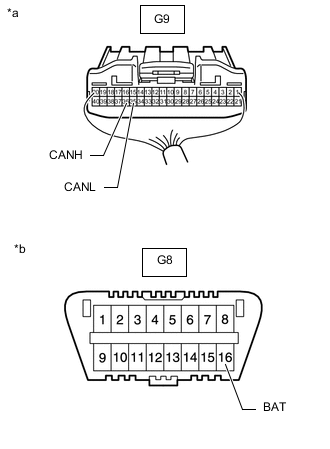
*a Rear view of wire harness connector
(to Combination Meter Assembly)
*b Front view of DLC3 Disconnect the combination meter assembly connector.
-
Measure the resistance according to the value(s) in the table below.
Standard Resistance Tester Connection Condition Specified Condition G9-36 (CANH) - G8-16 (BAT) Cable disconnected from negative (-) battery terminal 6 kΩ or higher G9-35 (CANL) - G8-16 (BAT) Cable disconnected from negative (-) battery terminal 6 kΩ or higher Result Proceed to OK NG
OK
REPLACE COMBINATION METER ASSEMBLY Click here
NG
REPAIR OR REPLACE CAN MAIN WIRE CONNECTED TO COMBINATION METER ASSEMBLY (CANH, CANL)
-
-
CONNECT CONNECTOR
-
Reconnect the No. 1 CAN junction connector.
Result Proceed to NEXT
NEXT
-
-
CHECK FOR SHORT TO B+ IN CAN BUS WIRE (ENGINE STOP AND START ECU BRANCH WIRE)
-
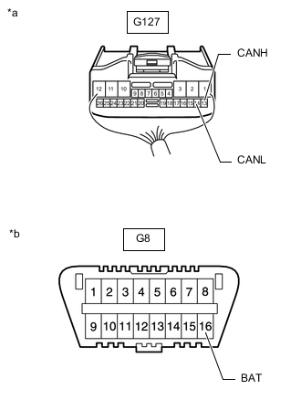
*a Rear view of wire harness connector
(to Engine Stop and Start ECU)
*b Front view of DLC3 Disconnect the engine stop and start ECU connector.
-
Measure the resistance according to the value(s) in the table below.
Standard Resistance Tester Connection Condition Specified Condition G127-13 (CANH) - G8-16 (BAT) Cable disconnected from negative (-) battery terminal 6 kΩ or higher G127-14 (CANL) - G8-16 (BAT) Cable disconnected from negative (-) battery terminal 6 kΩ or higher Result Proceed to OK NG
OK
REPLACE ENGINE STOP AND START ECU Click here
NG
REPAIR OR REPLACE CAN BRANCH WIRE CONNECTED TO ENGINE STOP AND START ECU (CANH, CANL)
-
-
CONNECT CONNECTOR
-
Reconnect the No. 1 CAN junction connector.
Result Proceed to NEXT
NEXT
-
-
CHECK FOR SHORT TO B+ IN CAN BUS WIRE (HEADLIGHT LEVELING ECU ASSEMBLY BRANCH WIRE)
-
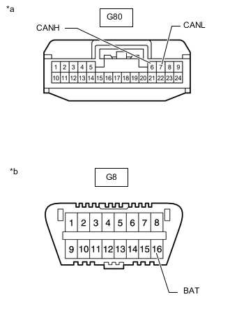
*a Front view of wire harness connector
(to Headlight Leveling ECU Assembly)
*b Front view of DLC3 Disconnect the headlight leveling ECU assembly connector.
-
Measure the resistance according to the value(s) in the table below.
Standard Resistance Tester Connection Condition Specified Condition G80-6 (CANH) - G8-16 (BAT) Cable disconnected from negative (-) battery terminal 6 kΩ or higher G80-7 (CANL) - G8-16 (BAT) Cable disconnected from negative (-) battery terminal 6 kΩ or higher Result Proceed to OK NG
OK
REPLACE HEADLIGHT LEVELING ECU ASSEMBLY Click here
NG
REPAIR OR REPLACE CAN BRANCH WIRE CONNECTED TO HEADLIGHT LEVELING ECU ASSEMBLY (CANH, CANL)
-