CAN COMMUNICATION SYSTEM(for LHD without Central Gateway ECU) SYSTEM DIAGRAM
-
V BUS
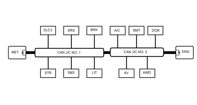

CAN Main Bus Line 
Terminating Resistor 
CAN Branch Line - - Connected to Code ECU/Sensor Name CAN DTC Storage Note V Bus DLC3 DLC3 - - ENG ECM Available - SMT Certification ECU (Smart Key ECU Assembly) Available
-
w/ Entry and Start System
-
Connected to LIN communication system
A/C Air Conditioning Amplifier Assembly Available
-
for Automatic Air Conditioning System or Manual Air Conditioning System
-
Connected to LIN communication system
AWD 4 Wheel Drive Control ECU Available for 4WD BRK Brake Actuator Assembly (Skid Control ECU) Available - SRS Airbag Sensor Assembly - w/ Airbag System LIT Headlight Leveling ECU Assembly Available for LED Headlight or w/ Headlight Cleaner System S&S Engine Stop and Start ECU Available w/ Stop and Start System STR Spiral with Sensor Cable Sub-assembly (Steering Angle Sensor) - w/ VSC MET Combination Meter Assembly Available - AV Navigation Receiver Assembly Available w/ Navigation System Radio and Display Receiver Assembly Available w/ Audio and Visual System (for Radio and Display Type) DCM Telematics Transceiver Available w/ Telematics Transceiver CAN J/C NO. 1 No. 1 CAN Junction Connector - - CAN J/C NO. 2 No. 2 CAN Junction Connector - - -