GENERATOR DISASSEMBLY

PROCEDURE
-
INSPECT GENERATOR WITH VACUUM PUMP ASSEMBLY
-
Mount the generator assembly in the vise between aluminum plates.
-
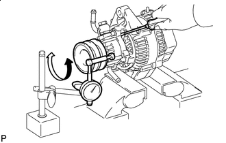

Turn Insert a screwdriver to hold the generator rotor assembly.
-
Install the bolt and nut to the outside of the pulley so that the bolt head and nut clamp the pulley, and then position a dial indicator as shown in the illustration.
-
Turn the pulley and measure the backlash between the generator rotor assembly and vacuum pump shaft.
Maximum backlash 1.6 mm (0.0630 in.) If the backlash is more than the maximum, replace the generator rotor assembly and vacuum pump shaft.
-
-
REMOVE VACUUM PUMP ASSEMBLY
-
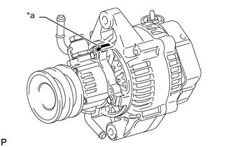
*a Matchmark Place matchmarks as shown in the illustration.
-
Remove the 4 bolts and vacuum pump assembly.
-
-
REMOVE GENERATOR REAR END COVER
-
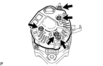
Remove the nut and terminal insulator.
-
Remove the bolt, 3 nuts, rectifier plate and generator rear end cover.
-
-
REMOVE GENERATOR BRUSH HOLDER ASSEMBLY
-
Remove the brush holder cover.
-
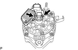
Remove the 2 screws and generator brush holder assembly.
-
Remove the plate seal.
-
-
REMOVE GENERATOR REGULATOR ASSEMBLY
-
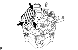
Remove the 3 screws and generator regulator assembly.
-
-
REMOVE GENERATOR HOLDER WITH RECTIFIER
-
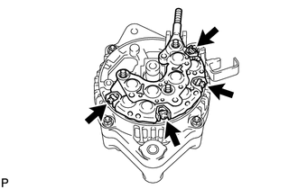
Remove the 4 screws and generator holder with rectifier.
-
Remove the 4 rubber insulators.
-
-
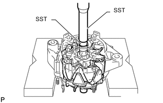
REMOVE GENERATOR RECTIFIER END FRAME
-
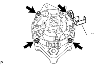
*1 Cord Clip Remove the 4 nuts and cord clip.
-
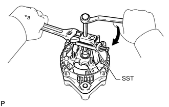
*a Hold Turn Using SST, remove the generator rectifier end frame.
- SST
- 09286-46011
-
Remove the washer from the generator rotor assembly.
-
-
INSPECT GENERATOR ROTOR ASSEMBLY
-
Using SST and a press, press out the generator rotor assembly.
- SST
- 09950-60010 ( 09951-00180 )
- 09950-70010 ( 09951-07100 )
-