CAUTION / NOTICE / HINT
The necessary procedures (adjustment, calibration, initialization, or registration) that must be performed after parts are removed, installed, or replaced during the brake actuator assembly removal/installation are shown below.
| Replacement Part or Procedure | Necessary Procedures | Effects/Inoperative when not Performed | Link |
|---|---|---|---|
| Skid control ECU (Brake actuator assembly) | Perform registration of rear differential lock identification information |
|
|
| Disconnect cable from negative battery terminal | Drive the vehicle until stop and start control is permitted (approximately 5 to 60 minutes) | Stop and start system | |
| Memorize steering angle neutral point | Pre-collision system |
PROCEDURE
- Click here
PRECAUTION
Note:After turning the ignition switch off, waiting time may be required before disconnecting the cable from the battery terminal. Therefore, make sure to read the disconnecting the cable from the battery terminal notice before proceeding with work.
- Click here
DISCONNECT CABLE FROM NEGATIVE BATTERY TERMINAL
CAUTION:Wait at least 90 seconds after disconnecting the cable from the negative (-) battery terminal to disable the SRS system.
Note:When disconnecting the cable, some systems need to be initialized after the cable is reconnected.
- Click here
DRAIN BRAKE FLUID
Note:Wash off brake fluid immediately if it comes in contact with any painted surface.
- Click here
REMOVE BRAKE ACTUATOR ASSEMBLY WITH BRACKET
-
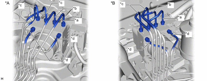
*A for LHD *B for RHD *a To Front Wheel Cylinder RH *b To Front Wheel Cylinder LH *c To Rear Wheel Cylinder *d From Master Cylinder Place tags or marks to identify the installation locations of each brake line.
-
*A for LHD *B for RHD 
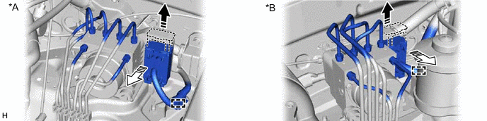
Lock Lever Released 
Connector Disconnected Release the latch of the actuator connector and disconnect the connector.
-
Detach the clamp from the brake actuator bracket.
-
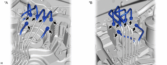
*A for LHD *B for RHD Using a union nut wrench, disconnect the 6 brake lines from the brake actuator.
-
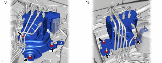
*A for LHD *B for RHD Remove the 3 nuts and brake actuator with bracket.
Note:Be careful not to damage the brake tubes.
-