STEERING ANGLE SENSOR(w/ VSC) REMOVAL
CAUTION / NOTICE / HINT
The necessary procedures (adjustment, calibration, initialization or registration) that must be performed after parts are removed, installed or replaced during the skid control buzzer removal/installation are shown below.
| Replacement Part or Procedure | Necessary Procedures | Effects / Inoperative when not Performed | Link |
|---|---|---|---|
| Disconnect cable from negative battery terminal | Drive the vehicle until stop and start control is permitted (approximately 5 to 60 minutes) | Stop and start system | |
| Memorize steering angle neutral point | Pre-collision system |
PROCEDURE
-
PRECAUTION
Note
After turning the ignition switch off, waiting time may be required before disconnecting the cable from the battery terminal. Therefore, make sure to read the disconnecting the cable from the battery terminal notice before proceeding with work.
-
DISCONNECT CABLE FROM NEGATIVE BATTERY TERMINAL
CAUTION:
Wait at least 90 seconds after disconnecting the cable from the negative (-) battery terminal to disable the SRS system.
Note
When disconnecting the cable, some systems need to be initialized after the cable is reconnected.
-
PLACE FRONT WHEELS FACING STRAIGHT AHEAD
-
REMOVE STEERING WHEEL ASSEMBLY
-
REMOVE LOWER STEERING COLUMN COVER
-
REMOVE UPPER STEERING COLUMN COVER
-
REMOVE SPIRAL WITH SENSOR CABLE SUB-ASSEMBLY
Note
-
Do not replace the spiral with sensor cable sub-assembly with the battery connected and the ignition switch ON.
-
Do not rotate the spiral with sensor cable sub-assembly with the battery connected and the ignition switch ON.
-
When rotating the spiral with sensor cable sub-assembly to check the operation of the sub-assembly (checking for abnormal noise, checking the Data List, etc.), make sure to perform the inspection with the steering wheel assembly installed.
-
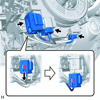
Slide the airbag connector slider as shown in the illustration and disconnect the airbag connector from the spiral with cable sensor sub-assembly.
-
Disconnect each connector from the spiral with sensor cable sub-assembly.
-
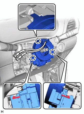
Detach the 3 claws and remove the spiral with sensor cable sub-assembly.
-