TIRE PRESSURE WARNING SYSTEM TERMINALS OF ECU
-
CHECK TIRE PRESSURE WARNING ECU AND RECEIVER

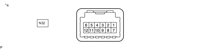
*a Front view of wire harness connector
(to Tire Pressure Warning ECU and Receiver)
- -
-
Disconnect the N32 tire pressure warning ECU and receiver connector and measure the voltage or resistance on the wire harness side.
Terminal No. (Symbol) Wiring Color Terminal Description Condition Specified Condition N32-1 (IG) - N32-12 (GND) G - W-B IG power source Ignition switch ON 10 to 16 V N32-12 (GND) - Body ground W-B - Body ground Ground Always Below 1 Ω -
Connect the N32 tire pressure warning ECU and receiver connector.
-
Measure the voltage and resistance according to the value(s) in the table below. If the result is not as specified, the ECU may have a malfunction.
Tech Tips
Measure the values on the wire harness side while the connector is connected.
*a Component with harness connected
(Tire Pressure Warning ECU and Receiver)
- - Terminal No. (Symbol) Wiring Color Terminal Description Condition Specified Condition N32-7 (CLSW) - N32-12 (GND) W-B - W-B Tire pressure warning reset switch
-
Ignition switch ON
-
Tire pressure warning reset switch on
Below 1.5 V
-
Ignition switch ON
-
Tire pressure warning reset switch off
8 to 15 V -
-