FRONT LOWER SUSPENSION ARM(for 2WD) INSTALLATION

CAUTION / NOTICE / HINT
Tech Tips
-
Use the same procedure for the RH and LH sides.
-
The procedure listed below is for the LH side.
PROCEDURE
-
INSTALL FRONT LOWER BALL JOINT ASSEMBLY LH
-
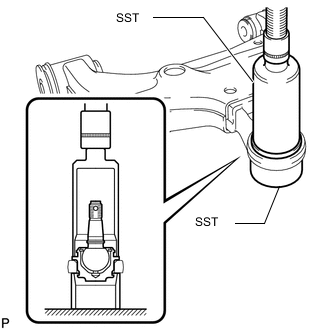
Using SST and press, press in a new lower ball joint.
- SST
- 09226-10010
- 09631-32020
-
Install a new snap ring.
Note
Make sure the snap ring is securely installed in the groove.
-
-
INSTALL FRONT LOWER NO. 1 ARM BUSH LH
-
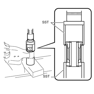
Using SST and a press, install a new front lower No. 1 arm bush LH.
- SST
- 09710-14013 ( 09710-00021 )
- 09710-20011 ( 09710-06041 )
- 09950-60010 ( 09951-00610 )
-
-
INSTALL FRONT LOWER NO. 2 ARM BUSH LH
-
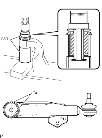
*a Bush Positioning Protrusion Using SST and a press, press in a new front lower No. 2 arm bush LH.
- SST
- 09710-14013 ( 09710-00021 )
- 09950-60010 ( 09951-00650 )
Note
Press the bush while making sure the bush positioning protrusions are perpendicular to the lower arm as shown in the illustration.
-
-
INSTALL FRONT LOWER BALL JOINT ATTACHMENT LH
-
Install the front lower ball joint attachment LH with the nut and a new cotter pin.
- Torque:
- 140 N*m { 1428 kgf*cm, 103 ft.*lbf }
-
-
TEMPORARILY INSTALL FRONT LOWER NO. 1 SUSPENSION ARM SUB-ASSEMBLY LH
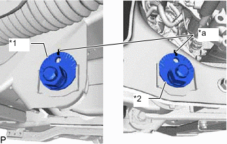
*1 No. 1 Camber Adjusting Cam *2 No. 2 Camber Adjusting Cam *a Matchmark
-
Temporarily install the front lower No. 1 suspension arm sub-assembly LH, and No. 1 and No. 2 camber adjusting cams with the 2 camber adjusting cams and 2 nuts.
-
Align the matchmarks on the No. 1 camber adjusting cam and No. 2 camber adjusting cam with the corresponding matchmarks on the vehicle frame.
-
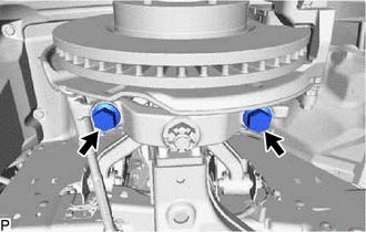
Install the front lower ball joint attachment LH with the 2 bolts.
- Torque:
- 160 N*m { 1632 kgf*cm, 118 ft.*lbf }
-
-
INSTALL FRONT NO. 1 SPRING BUMPER SUB-ASSEMBLY
-
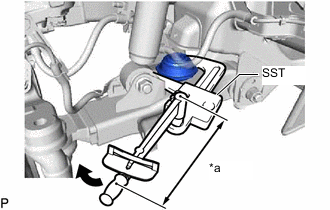
*a Torque Wrench Fulcrum Length Using SST, install the front No. 1 spring bumper sub-assembly to the front lower No. 1 suspension arm sub-assembly LH.
- SST
- 09922-10010
- Torque:
- Specified tightening torque
- 31 N*m { 316 kgf*cm, 23 ft.*lbf }
Tech Tips
-
Calculate the torque wrench reading when changing the fulcrum length of the torque wrench.
-
When using SST (fulcrum length of 112.5 mm (4.4291 in.)) + torque wrench (fulcrum length of 300 mm (11.8110 in.)): 22.5 N*m (229 kgf*cm, 17 ft.*lbf)
-
-
TEMPORARILY INSTALL FRONT SHOCK ABSORBER WITH COIL SPRING
-
Temporarily install the front shock absorber with coil spring with the bolt and nut.
-
-
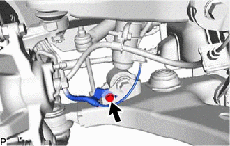
CONNECT FRONT STABILIZER LINK ASSEMBLY LH
-
Connect the front stabilizer link assembly LH to the front lower No. 1 suspension arm sub-assembly LH with the nut.
- Torque:
- 78 N*m { 795 kgf*cm, 58 ft.*lbf }
Tech Tips
If the ball joint turns together with the nut, use a 6 mm hexagon wrench to hold the stud in place.
-
-
CONNECT FRONT SPEED SENSOR LH (w/ ABS)
-
Connect the front speed sensor LH with the bolt.
- Torque:
- 32 N*m { 326 kgf*cm, 24 ft.*lbf }
-
-
INSTALL NO. 1 ENGINE UNDER COVER ASSEMBLY (w/ Engine Under Cover Assembly)
-
INSTALL FRONT WHEEL
-
STABILIZE SUSPENSION
-
TIGHTEN FRONT LOWER NO. 1 SUSPENSION ARM SUB-ASSEMBLY LH
-
Tighten the 2 nuts.
- Torque:
- 210 N*m { 2141 kgf*cm, 155 ft.*lbf }
-
-
TIGHTEN FRONT SHOCK ABSORBER WITH COIL SPRING
-
Fix the nut in place and tighten the bolt.
- Torque:
- 110 N*m { 1122 kgf*cm, 81 ft.*lbf }
Note
Do not tighten the nut.
-
-
INSPECT AND ADJUST FRONT WHEEL ALIGNMENT