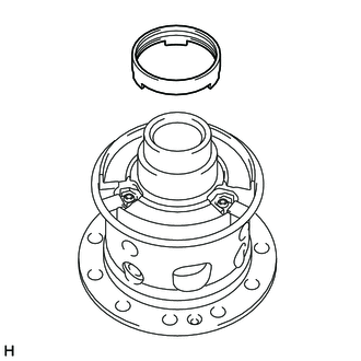
REAR DIFFERENTIAL CARRIER ASSEMBLY(for DANA Made w/ Differential Lock) DISASSEMBLY

CAUTION / NOTICE / HINT
Tech Tips
The following procedures are for BD22 (w/ Differential Lock).
PROCEDURE
-
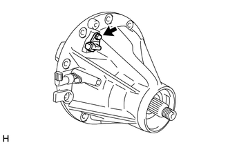
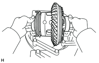
SECURE REAR DIFFERENTIAL CARRIER ASSEMBLY
-
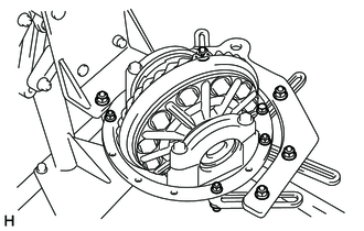
Secure the rear differential carrier assembly.
-
-
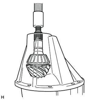
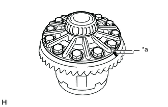
INSPECT REAR DRIVE PINION COMPANION FLANGE SUB-ASSEMBLY
-
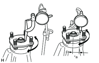
*a 36 mm (1.42 in.) Using a dial indicator, measure the runout of the companion flange vertically and laterally.
Maximum Runout Runout Maximum Vertical runout 0.10 mm (0.00394 in.) Lateral runout 0.10 mm (0.00394 in.) If the runout is more than the maximum, replace the companion flange.
-
-
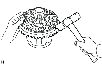
INSPECT DIFFERENTIAL RING GEAR BACKLASH
-
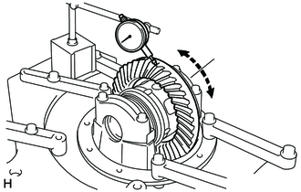
Using a dial indicator, measure the backlash of the differential ring gear.
Standard backlash 0.13 to 0.20 mm (0.00512 to 0.00787 in.)
-
If the backlash is not within the specification, adjust the side bearing preload or perform repairs as necessary.
Tech Tips
Perform the measurement at 3 or more positions around the circumference of the ring gear.
-
-
-
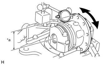
INSPECT TOTAL PRELOAD
-
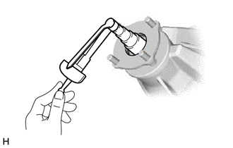
Using a torque wrench, measure the preload with the teeth of the differential drive pinion and differential ring gear in contact.
If the result is not as specified, adjust the preload.
Standard Total Preload Reduction Ratio Specified Condition 3.583 2.27 to 4.30 N*m (24 to 43 kgf*cm, 21 to 38 in.*lbf) 3.909 2.25 to 4.24 N*m (23 to 43 kgf*cm, 20 to 37 in.*lbf) 4.100 2.24 to 4.22 N*m (23 to 43 kgf*cm, 20 to 37 in.*lbf) 4.300 2.23 to 4.19 N*m (23 to 42 kgf*cm, 20 to 37 in.*lbf) 4.555 2.21 to 4.16 N*m (23 to 42 kgf*cm, 20 to 36 in.*lbf)
-
-
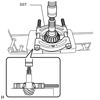
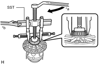
REMOVE REAR DRIVE PINION NUT
-

Using a chisel and hammer, stake the rear drive pinion nut.
- SST
- 09930-00010 ( 09931-00010, 09931-00020 )
-
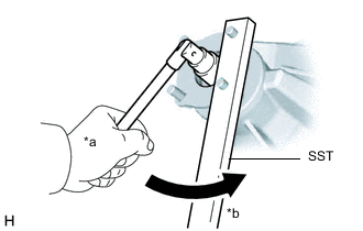
*a Turn *b Hold Using SST to hold the companion flange in place, remove the rear drive pinion nut.
- SST
- 09330-00021 ( 09330-00030 )
-
-
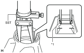
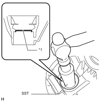
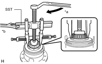
REMOVE REAR DRIVE PINION COMPANION FLANGE SUB-ASSEMBLY WITH DUST DEFLECTOR
-
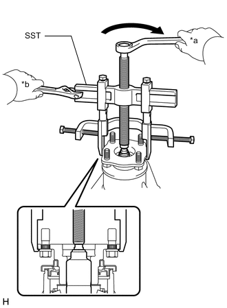
*a Turn *b Hold Using SST, remove the rear drive pinion companion flange sub-assembly with dust deflector.
- SST
- 09950-40011 ( 09951-04010, 09953-04020, 09954-04010, 09955-04061 )
Note
Before using SST (center bolt), apply hypoid gear oil to its threads and tip.
-
-
REMOVE REAR DIFFERENTIAL CARRIER OIL SEAL
-
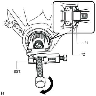
*1 Rear Differential Carrier Oil Seal *2 Rear Differential Drive Pinion Oil Slinger Using SST, remove the rear differential carrier oil seal.
- SST
- 09308-10010
-
-
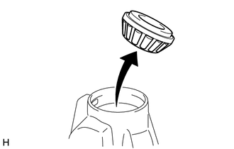
REMOVE REAR DIFFERENTIAL DRIVE PINION OIL SLINGER
-
Remove the rear differential drive pinion oil slinger from the differential drive pinion.
-
-
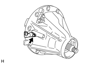
REMOVE WIRING HARNESS CONNECTOR
-
Remove the bolt and wiring harness connector.
-
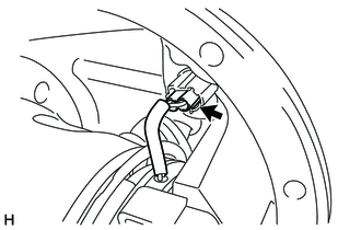
Disconnect the connector.
-
-
REMOVE DIFFERENTIAL BEARING CAP
-
*a Matchmark Place matchmarks on the differential bearing cap and differential carrier.
-
Remove the 4 bolts and 2 differential bearing caps.
-
Remove the 2 plate washers.
*a LH Side (Ring Gear Side) *b RH Side (Differential Lock Coil Side) Tech Tips
-
Put identification marks on the plate washers to show the location for installation (LH side (ring gear side) or RH side (differential lock coil side)), or keep them separate so that they can be distinguished.
-
Measure the thickness of each plate washers and note it.
-
-
-
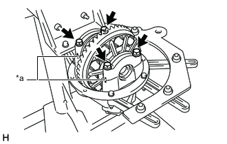
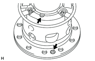
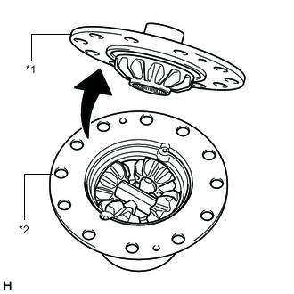
REMOVE ELECTRONIC DIFFERENTIAL LOCK CASE SUB-ASSEMBLY
-
Remove the electronic differential lock case sub-assembly from the differential carrier.
Tech Tips
Tag the 2 rear differential case bearings (outer) so that they can be reinstalled in the correct locations.
-
-
REMOVE NO. 1 TRANSFER INDICATOR SWITCH (REAR DIFFERENTIAL LOCK POSITION SWITCH)
-
Remove the bolt and No. 1 transfer indicator switch (rear differential lock position switch).
-
-
REMOVE DIFFERENTIAL DRIVE PINION
-
Using a press, remove the differential drive pinion with rear differential drive pinion bearing spacer from the differential carrier.
Note
Do not drop the differential drive pinion.
-
-
REMOVE REAR DIFFERENTIAL DRIVE PINION BEARING SPACER
-
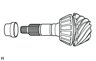
Remove the rear differential drive pinion bearing spacer from the differential drive pinion.
-
-
REMOVE REAR DRIVE PINION REAR TAPERED ROLLER BEARING
-
Using SST and a press, press out the rear drive pinion rear tapered roller bearing (inner) from the differential drive pinion.
- SST
- 09555-55010
Note
Do not drop the differential drive pinion.
Tech Tips
If the differential drive pinion or differential ring gear is damaged, replace them as a set.
-
-
REMOVE REAR DRIVE PINION FRONT TAPERED ROLLER BEARING
-
Remove the rear drive pinion front tapered roller bearing (inner) from the differential carrier.
-
-
REMOVE REAR DRIVE PINION FRONT TAPERED ROLLER BEARING
-
*1 Rear Drive Pinion Front Tapered Roller Bearing (Outer) Using SST, remove the rear drive pinion front tapered roller bearing (outer) from the differential carrier.
- SST
- 09308-00010
-
-
REMOVE DIFFERENTIAL OIL STORAGE RING
-
*1 Differential Oil Storage Ring Using SST and a hammer, tap out the differential oil storage ring from the differential carrier.
- SST
- 09316-60011 ( 09316-00011 )
-
-
REMOVE REAR DRIVE PINION REAR TAPERED ROLLER BEARING
-
Using a brass bar and hammer, tap out the rear drive pinion rear tapered roller bearing (outer) and adjusting shim from the differential carrier.
If the bearing is damaged during removal, replace it.
-
-
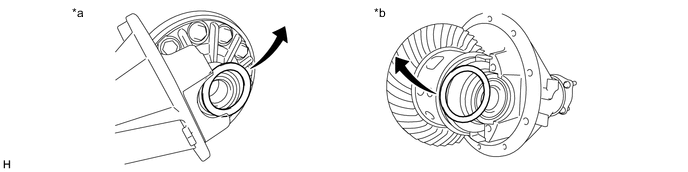
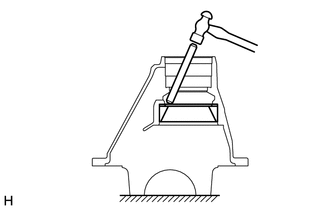
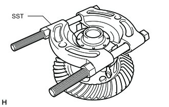
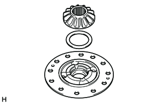
REMOVE DIFFERENTIAL RING GEAR
-
*a Matchmark Place matchmarks on the differential ring gear and differential case.
-
Remove the 12 differential ring gear set bolts.
-
Using a plastic-faced hammer, tap on the differential ring gear to remove it from the differential case.
Note
Do not damage the position plate when removing the ring gear.
-
-
INSPECT DIFFERENTIAL CASE ASSEMBLY RUNOUT
Tech Tips
If the ring gear runout is within the specified value (refer to the "Inspect Runout of Differential Ring Gear" procedure above), skip this step.
-
Install the rear differential case bearings (outer) to the electronic differential lock case sub-assembly.
-
Install the electronic differential lock case sub-assembly to the differential carrier.
-
Install the 2 plate washers.
-
Install the 2 differential bearing caps to the differential carrier with the 4 bolts.
- Torque:
- 140 N*m { 1428 kgf*cm, 103 ft.*lbf }
-
*a 92 mm (3.62 in.) Using a dial indicator, measure the electronic differential case runout.
Maximum runout 0.07 mm (0.00276 in.) -
Remove the 4 bolts and 2 differential bearing caps.
-
Remove the 2 plate washers.
-
Remove the electronic differential lock case sub-assembly.
-
Remove the rear differential case bearings (outer).
-
-
REMOVE REAR DIFFERENTIAL CASE BEARING
-
*a Turn *b Hold for LH Side (Ring Gear Side):
-
Using SST, remove the rear differential case bearing (inner) from the electronic differential lock case sub-assembly.
- SST
- 09950-40011 ( 09951-04020, 09952-04010, 09953-04030, 09954-04010, 09955-04061, 09957-04010, 09958-04011 )
- 09950-60010 ( 09951-00640 )
Tech Tips
Do not remove the case bearings when not replacing the electronic differential lock case sub-assembly.
-
-
for RH Side (Differential Lock Coil Side):
-
*a Turn *b Hold Using SST, remove the rear differential case bearing (inner) from the electronic differential lock case sub-assembly.
- SST
- 09950-40011 ( 09951-04020, 09952-04010, 09953-04030, 09954-04010, 09955-04011, 09957-04010, 09958-04011 )
- 09950-60010 ( 09951-00640 )
Tech Tips
Do not remove the case bearings when not replacing the electronic differential lock case sub-assembly.
-
-
-
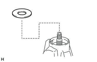
REMOVE DIFFERENTIAL SOLENOID WASHER
-
Tighten the 2 SST nuts evenly and remove the differential solenoid washer from the electronic differential lock case sub-assembly.
- SST
- 09555-55010
-
-
REMOVE DIFFERENTIAL LOCK COIL
-
Remove the differential lock coil from the electronic differential lock case sub-assembly.
-
-
REMOVE DIFFERENTIAL LOCK PLUNGER
-
Remove the differential lock plunger from the rear differential case sub-assembly.
-
-
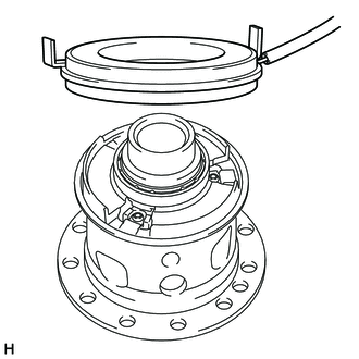
DISASSEMBLE REAR DIFFERENTIAL CASE SUB-ASSEMBLY
-
Remove the 2 screws.
-
*1 Differential Case LH *2 Differential Case RH Remove the differential case LH from the differential case RH.
-
Remove the differential side gear and rear No. 1 differential side gear thrust washer from the differential case LH.
-
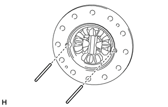
Remove the 2 rear differential pinion shaft pins.
-
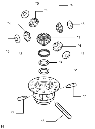
*1 Differential Side Gear (Dog Clutch) *2 Rear No. 2 Differential Side Gear Thrust Washer *3 Rear No. 3 Differential Side Gear Thrust Washer *4 Differential Pinion *5 Rear Differential Pinion Thrust Washer *6 Rear Differential Pinion Shaft *7 Rear No. 2 Differential Pinion Shaft *8 Differential Lock Spring Remove the following parts from the differential case RH.
-
Differential side gear (Dog clutch)
-
Rear No. 2 differential side gear thrust washer
-
Rear No. 3 differential side gear thrust washer
-
Differential pinion (4 pieces)
-
Rear differential pinion thrust washer (4 pieces)
-
Rear differential pinion shaft
-
Rear No. 2 differential pinion shaft (2 pieces)
-
Differential lock spring
-
-
-
REMOVE DIFFERENTIAL LOCK POSITION PLATE
-
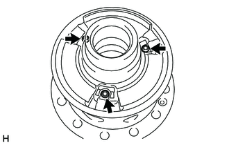
Using a T25 ''TORX'' socket wrench, remove the 3 screws from the differential lock position plate.
-
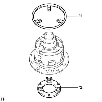
*1 Differential Lock Position Plate *2 Differential Lock Cam Ring Remove the differential lock position plate from the differential case RH.
-
-
REMOVE DIFFERENTIAL LOCK CAM RING
-
Remove the differential lock cam ring from the differential case RH.
-
-
INSPECT DIFFERENTIAL GEAR KIT
-
Check that the differential pinion and differential side gear are not damaged.
If the differential pinion or differential side gear is damaged, replace the differential gear kit.
-
-
INSPECT DIFFERENTIAL CASE
-
Check that the differential case is not damaged.
If the differential case is damaged, replace it.
-