DIFFERENTIAL SYSTEM(w/ Differential Lock) Lock Switch Circuit
WIRING DIAGRAM
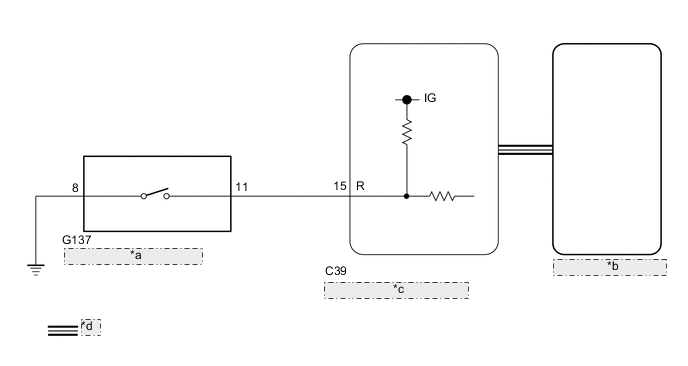
| *a | Differential Lock Switch |
| *b | Combination Meter Assembly |
| *c | 4 Wheel Drive Control ECU |
| *d | CAN Communication Line |
PROCEDURE
-
CHECK REAR DIFFERENTIAL LOCK INDICATOR LIGHT
-
Turn the ignition switch to ON.
-
except Pre-Runner:
Finish switching to L4.
-
Check the rear differential lock indicator light.
-
Press the differential lock switch.
-
After 60 seconds, check the rear differential lock indicator light.
Result Result Proceed to Rear differential lock indicator light blinks or illuminates A Rear differential lock indicator light remains off regardless of switch operation B Rear differential lock indicator light remains illuminated regardless of switch operation C Rear differential lock indicator light rapidly blinks D
-
Blinking: Blinks at 0.5 second intervals (0.5 seconds on and 0.5 seconds off)
-
Rapidly blinking: Blinks at 0.25 second intervals (0.25 seconds on and 0.25 seconds off)
-
A 
END
C 
CHECK CAN COMMUNICATION LINE Click here
D
GO TO DTC P17CC Click here
B 
-
-
CHECK CAN COMMUNICATION LINE
-
Select "Bus Check" from the System Selection Menu screen, and follow the prompts on the screen to inspect the CAN Bus.
for LHD without Central Gateway ECU: Click here
for RHD without Central Gateway ECU: Click here
for LHD with Central Gateway ECU: Click here
for RHD with Central Gateway ECU: Click here
OK "Bus Check" indicates no malfunctions in CAN communication. Result Proceed to OK NG
NG
CHECK CAN COMMUNICATION SYSTEM for LHD without Central Gateway ECU: Click here
CHECK CAN COMMUNICATION SYSTEM for RHD without Central Gateway ECU: Click here
CHECK CAN COMMUNICATION SYSTEM for LHD with Central Gateway ECU: Click here
CHECK CAN COMMUNICATION SYSTEM for RHD with Central Gateway ECU: Click hereOK
-
-
READ VALUE USING GTS (DIFFERENTIAL LOCK SWITCH)
-
Turn the ignition switch off.
-
Connect the GTS to the DLC3.
-
Turn the GTS on.
-
Turn the ignition switch to ON.
-
Enter the following menus: Powertrain / Four Wheel Drive / Data List.
-
According to the display on the GTS, read the Data List.
Powertrain > Four Wheel Drive > Data ListTester Display Measurement Item Range Normal Condition Diagnostic Note Rear Differential Lock Control SW (R) Differential lock switch status (differential lock switch input signal of R terminal on ECU side) ON or OFF ON: Switch pressed and held
OFF: Switch not pressed
-
Powertrain > Four Wheel Drive > Data ListTester Display Rear Differential Lock Control SW (R) OK Display changes according to differential lock switch operation. Result Proceed to OK NG
NG
INSPECT DIFFERENTIAL LOCK SWITCH Click here
OK
-
-
INSPECT COMBINATION METER ASSEMBLY
-
Turn the ignition switch off.
-
Perform Active Test of the combination meter assembly using the GTS.
Body Electrical > Combination Meter > Active TestTester Display Indicat. Rr DIFF LOCK -
Check the combination meter assembly.
OK The rear differential lock indicator light turns on or off in accordance with the GTS. Result Proceed to OK NG
OK
REPLACE 4 WHEEL DRIVE CONTROL ECU Click here
NG
CHECK METER / GAUGE SYSTEM Click here
-
-
INSPECT DIFFERENTIAL LOCK SWITCH
-
Remove the differential lock switch.
Click here
-
Inspect the differential lock switch.
OK The differential lock switch operates normally. Result Result OK NG
NG
REPLACE DIFFERENTIAL LOCK SWITCH Click here
OK
-
-
CHECK HARNESS AND CONNECTOR (4 WHEEL DRIVE CONTROL ECU - DIFFERENTIAL LOCK SWITCH)
-
Disconnect the C39 4 wheel drive control ECU connector.
-
Disconnect the G137 differential lock switch connector.
-
Measure the resistance according to the value(s) in the table below.
Standard Resistance Tester Connection Condition Specified Condition C39-15 (R) - G137-11 Always Below 1 Ω G137-8 - Body ground Always Below 1 Ω Result Proceed to OK NG
OK
REPLACE 4 WHEEL DRIVE CONTROL ECU Click here
NG
REPAIR OR REPLACE HARNESS OR CONNECTOR
-
-
CHECK CAN COMMUNICATION LINE
-
Select "Bus Check" from the System Selection Menu screen, and follow the prompts on the screen to inspect the CAN Bus.
for LHD without Central Gateway ECU: Click here
for RHD without Central Gateway ECU: Click here
for LHD with Central Gateway ECU: Click here
for RHD with Central Gateway ECU: Click here
OK "Bus Check" indicates no malfunctions in CAN communication. Result Proceed to OK NG
NG
CHECK CAN COMMUNICATION SYSTEM for LHD without Central Gateway ECU: Click here
CHECK CAN COMMUNICATION SYSTEM for RHD without Central Gateway ECU: Click here
CHECK CAN COMMUNICATION SYSTEM for LHD with Central Gateway ECU: Click here
CHECK CAN COMMUNICATION SYSTEM for RHD with Central Gateway ECU: Click hereOK
-
-
READ VALUE USING GTS (REAR DIFFERENTIAL LOCK INDICATOR LIGHT)
-
Turn the ignition switch off.
-
Connect the GTS to the DLC3.
-
Turn the GTS on.
-
Turn the ignition switch to ON.
-
Enter the following menus: Powertrain / Four Wheel Drive / Data List.
-
According to the display on the GTS, read the Data List.
Powertrain > Four Wheel Drive > Data ListTester Display Measurement Item Range Normal Condition Diagnostic Note Rear Differential Lock Indicator Request Rear differential lock indicator light request Blink4*, Blink3, Blink2, Blink1, ON or OFF
-
Blink3: Indicator light rapidly blinks
-
Blink2: Indicator light blinks 3 times
-
Blink1: Indicator light blinks
-
ON: Indicator light illuminates
-
OFF: Indicator light turns off
-
Blinking: 0.5 second intervals (0.5 seconds on and 0.5 seconds off)
-
Rapidly blinking: 0.25 second intervals (0.25 seconds on and 0.25 seconds off)
*: Item not supported, therefore not displayed
Powertrain > Four Wheel Drive > Data ListTester Display Rear Differential Lock Indicator Request -
-
except Pre-Runner:
Finish switching to L4.
-
Turn the differential lock switch on and off several times and check the GTS display condition of the rear differential lock indicator light.
Result Result Proceed to Data List continues to display ON even when differential lock switch is operated A Data List display changes according to differential lock switch operation B
A
REPLACE 4 WHEEL DRIVE CONTROL ECU Click here
B
CHECK METER / GAUGE SYSTEM Click here
-