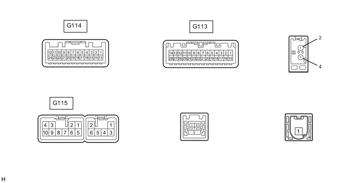
REAR VIEW MONITOR SYSTEM(for Navigation Receiver Type) TERMINALS OF ECU
-
CHECK NAVIGATION RECEIVER ASSEMBLY
-
Disconnect the G113 and G115 navigation receiver assembly connectors.
-
Measure the voltage and resistance according to the value(s) in the table below.
Terminal No. (Symbol) Wiring Color Terminal Description Condition Specified Condition G113-1 (IG) - Body ground G - Body ground Power source of IG Ignition switch off Below 1 V Ignition switch ON 11 to 14 V G115-3 (ACC1) - Body ground GR - Body ground Power source of ACC Ignition switch off Below 1 V Ignition switch ACC 11 to 14 V G115-4 (+B1) - Body ground SB - Body ground Battery Always 11 to 14 V G115-7 (GND1) - Body ground BR - Body ground Ground Always Below 1 Ω -
Reconnect the G113 and G115 navigation receiver assembly connectors.
-
Measure the voltage and check for waveform according to the value(s) in the table below.
Terminal No. (Symbol) Wiring Color Terminal Description Condition Specified Condition G113-2 (REV) - Body ground R - Body ground Reverse signal Ignition switch ON, shift lever in R 7.5 to 14 V Ignition switch ON, shift lever not in R Below 1 V G114-12 (V+) - G114-24 (V-) R - W Display signal Ignition switch ON, shift lever in R Pulse generation (See waveform 1) Ignition switch ON, shift lever in R, screen blacked out by covering camera lens Pulse generation (See waveform 2) G114-11 (CA+) - G114-23 (CGND) B - Shielded Power source Ignition switch ACC 5.5 to 7.05 V G114-23 (CGND) - Body ground Shielded - Body ground Shielding Always Below 1 V -
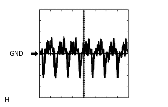
Using an oscilloscope, check waveform 1.
Measurement Condition Item Content Terminal No. (Symbol) G114-12 (V+) - G114-24 (V-) Tool Setting 200 mV/DIV., 50 μsec./DIV. Condition Ignition switch ON, shift lever in R -
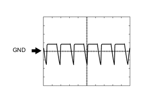
Using an oscilloscope, check waveform 2.
Measurement Condition Item Content Terminal No. (Symbol) G114-12 (V+) - G114-24 (V-) Tool Setting 200 mV/DIV., 50 μsec./DIV. Condition Ignition switch ON, shift lever in R, screen blacked out by covering camera lens
-