FRONT AXLE HUB(for 2WD) INSTALLATION

CAUTION / NOTICE / HINT
Tech Tips
-
Use the same procedure for the RH and LH sides.
-
The procedure listed below is for the LH side.
PROCEDURE
-
INSTALL FRONT INNER AXLE HUB BEARING LH
-
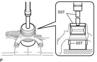
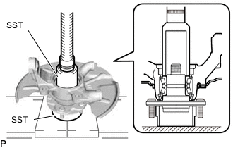
Using SST and a press, press a new front inner axle hub bearing LH (outer race) into the steering knuckle LH.
- SST
- 09527-17011
- 09950-60020 ( 09951-00750 )
- 09950-70010 ( 09951-07100 )
-
-
INSTALL FRONT AXLE HUB HOLE SNAP RING LH
-
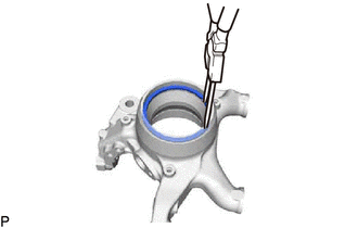
Using a snap ring pliers, install a new front axle hub hole snap ring LH to the steering knuckle LH.
-
-
INSTALL FRONT AXLE HUB OIL SEAL LH
-
Install a new front inner axle hub bearing LH (outer side inner bearing) to the steering knuckle LH.
-
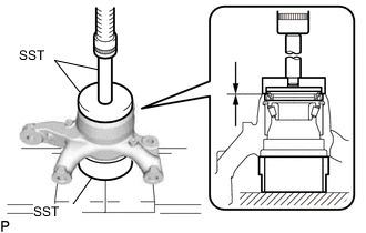
Using SST and a press, press a new front axle hub oil seal LH into the steering knuckle LH.
- SST
- 09527-17011
- 09950-60020 ( 09951-00810 )
- 09950-70010 ( 09951-07100 )
-
Apply MP grease to the lip of the front axle hub oil seal LH.
-
Install the dust cover with the 3 bolts.
- Torque:
- 8.0 N*m { 82 kgf*cm, 71 in.*lbf }
-
-
INSTALL FRONT AXLE HUB SUB-ASSEMBLY LH
-
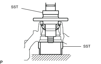
Using SST and a press, press the front axle hub sub-assembly LH into the steering knuckle LH.
- SST
- 09950-60010 ( 09951-00600 )
- 09527-17011
-
Using SST and a press, press a new front inner axle hub bearing LH (inner side inner race) into the front axle hub sub-assembly LH.
- SST
- 09223-00010
- 09527-17011
-
Install 3 new front axle hub bolts.
-
-
INSTALL FRONT INNER WHEEL BEARING SPACER LH (w/o ABS)
-
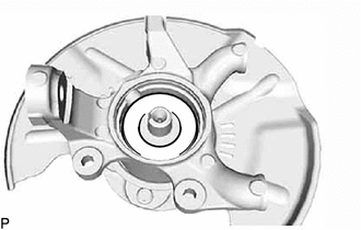
Install the front inner wheel bearing spacer LH.
-
-
INSTALL FRONT SKID CONTROL ROTOR (w/ ABS)
-
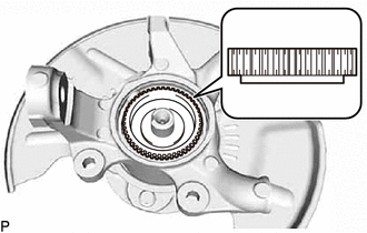
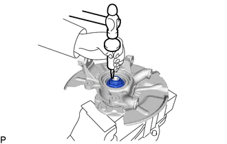
Install the front skid control rotor as shown in the illustration.
Note
Take care not to scratch the serration of the front skid control rotor.
-
-
INSTALL FRONT AXLE SHAFT NUT LH
-
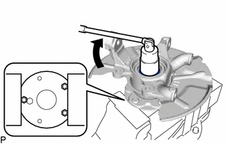
Using a 36 mm socket wrench, install a new front axle shaft nut LH to the front axle hub sub-assembly LH.
- Torque:
- 199 N*m { 2029 kgf*cm, 147 ft.*lbf }
-
Using a chisel and hammer, stake the front axle shaft nut LH.
Note
Do not scratch the serration of the front skid control rotor.
-
-
INSTALL KNUCKLE GREASE RETAINER CAP LH
-
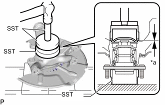
*a Clearance Using SST and a hammer, tap the knuckle grease retainer cap LH.
- SST
- 09527-17011
- 09950-60020 ( 09951-00910 )
- 09950-70010 ( 09951-07150 )
Standard clearance 0.2 mm (0.0079 in.) or less Note
Do not damage the knuckle grease retainer cap LH.
-
-
CONNECT FRONT UPPER SUSPENSION ARM ASSEMBLY LH
-
Connect the front upper suspension arm assembly LH to the steering knuckle LH with a new nut.
- Torque:
- 110 N*m { 1122 kgf*cm, 81 ft.*lbf }
-
Install a new clip.
Note
If the holes for the clip are not aligned, tighten the nut an additional 60°.
-
-
CONNECT FRONT LOWER NO. 1 SUSPENSION ARM ASSEMBLY LH
-
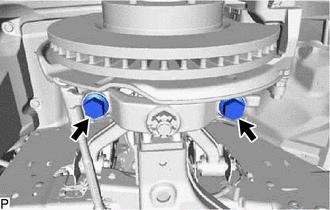
Connect the front lower No. 1 suspension arm LH to the steering knuckle LH with the 2 bolts.
- Torque:
- 160 N*m { 1632 kgf*cm, 118 ft.*lbf }
-
-
CONNECT TIE ROD END SUB-ASSEMBLY LH
-
INSTALL FRONT DISC
-
INSTALL FRONT DISC BRAKE CYLINDER MOUNTING LH
-
INSTALL FRONT DISC BRAKE CYLINDER ASSEMBLY LH
-
CONNECT FRONT FLEXIBLE HOSE
-
CONNECT FRONT SPEED SENSOR LH (w/ ABS)
-
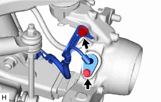
Install the front speed sensor LH with the bolt.
- Torque:
- 8.5 N*m { 87 kgf*cm, 75 in.*lbf }
Note
-
Make sure there are no pieces of iron or other foreign matter attached to the front speed sensor LH tip.
-
While inserting the front speed sensor LH into the knuckle hole, do not strike or damage the sensor tip.
-
After installing the front speed sensor LH, make sure there is no clearance or foreign matter between the sensor stay part and the knuckle.
-
When installing the front speed sensor LH, do not twist the wire harness.
-
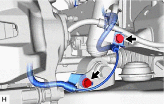
Install the harness clamp to the steering knuckle with the bolt.
- Torque:
- 32 N*m { 326 kgf*cm, 24 ft.*lbf }
Note
-
When installing the harness clamp, do not twist the wire harness.
-
Make sure the clamp rotation stopper touches the installation position.
-
Install the harness clamp to the front lower arm bracket with the bolt.
- Torque:
- 32 N*m { 326 kgf*cm, 24 ft.*lbf }
Note
-
When installing the harness clamp, do not twist the wire harness.
-
Make sure the harness clamp rotation stopper touches the installation position.
-
Install the harness clamp to the front absorber bracket with the bolt.
- Torque:
- 32 N*m { 326 kgf*cm, 24 ft.*lbf }
Note
-
When installing the harness clamp, do not twist the wire harness.
-
Make sure the harness clamp rotation stopper touches the installation position.
-
-
INSTALL FRONT WHEEL
-
INSPECT AND ADJUST FRONT WHEEL ALIGNMENT
-
CHECK ABS SPEED SENSOR SIGNAL (w/ ABS)
-
w/ VSC:
-
w/o VSC:
-