PROPELLER SHAFT ASSEMBLY(for TSAM Made) REASSEMBLY

CAUTION / NOTICE / HINT
Note
-
When using a vise, place aluminum plates between the part and vise.
-
When using a vise, do not overtighten it.
Tech Tips
The following chart describes vehicle types A and B, which are referred to throughout the procedure.
| Vehicle Type A | Vehicle Type B | ||
|---|---|---|---|
| Engine Type | Transmission Type | Engine Type | Transmission Type |
| 1GR-FE | AC60E | 1GD-FTV | AC60E |
| 2GD-FTV | R151 | RC61 | |
| 2KD-FTV | R151 | 2GD-FTV | RC60 |
| 1TR-FE | R151 | 2KD-FTV | RC61 |
| 2TR-FE | R151 | - | - |
| Vehicle Type A | Vehicle Type B | ||
|---|---|---|---|
| Engine Type | Transmission Type | Engine Type | Transmission Type |
| 1GR-FE | AC60F | 1KD-FTV | RC61F |
| 1KD-FTV | A750F | 1GD-FTV | AC60F |
| 5L-E | R151F | RC61F | |
| 2TR-FE | AC60F | 2GD-FTV | RC60F |
| R151F | 2KD-FTV | RC61F | |
PROCEDURE
-
INSTALL CENTER NO. 1 SUPPORT BEARING ASSEMBLY
-
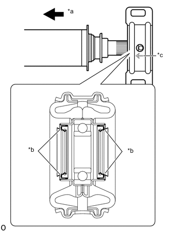
*a Front Side *b Seal *c Engraved Arrow Install the center No. 1 support bearing assembly to the intermediate shaft.
Note
-
Carefully insert the part so that the seal does not invert.
-
Make sure to install the part so that the engraved arrow faces the front of the vehicle.
-
-
Install the 2 washers to the intermediate shaft.
-
*a Matchmark Align the matchmarks on the center yoke and intermediate shaft, and then install the center yoke to the intermediate shaft.
-
Install the washer to the intermediate shaft.
-
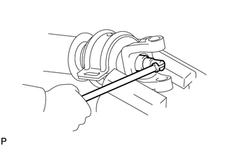
Clamp the center yoke in a vise between aluminum plates and press the bearing into position by installing a new lock nut.
- Torque:
- 127.5 N*m { 1300 kgf*cm, 94 ft.*lbf }
-
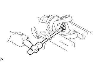
Using a chisel and hammer, stake the lock nut.
Note
-
Fully stake the lock nut along the entire groove.
-
Do not damage the threads of the intermediate shaft.
-
-
-
INSTALL UNIVERSAL JOINT SPIDER ASSEMBLY
Tech Tips
Use the same procedure for all universal joint spider assemblies.
-
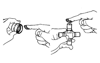
Apply grease to a new spider and new spider bearings.
Grease Lithium base chassis grease NLGI No. 2 Note
Do not apply too much grease.
-
Install the universal joint spider assembly to the flange yoke.
-
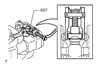
Using SST, install the spider bearing to the universal joint spider assembly.
- SST
- 09332-25010
-
Using SST, adjust both spider bearings so that the snap ring grooves are as wide as possible and equal in width.
- SST
- 09332-25010
-
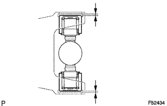
Install 2 new snap rings to the installed spider bearings. The snap rings must have equal thickness and allow 0 to 0.05 mm (0 to 0.00196 in.) of axial play.
Note
While the installed snap rings should have equal thickness, if the axial play is greater than 0.05 mm (0.00196 in.), select 2 snap rings that have as close to the same thickness as possible.
Standard Snap Ring Thickness *: For cup with grease nipple.for Vehicle Type A Part No. Color Thickness 90080-52038 Blue 1.638 mm (0.0645 in.) 90080-52039 Yellow 1.588 mm (0.0625 in.) 90080-52040 White 1.537 mm (0.0605 in.) 90080-52041 Black 1.486 mm (0.0585 in.) 90080-52042 Copper 1.511 mm (0.0595 in.) 90080-52156* - -
*: For cup with grease nipple.for Vehicle Type B Part No. Mark Thickness 90521-A0003* Black 1.486 mm (0.0587 in.) 90521-A0005* Yellow 1.588 mm (0.0626 in.) 90521-A0006* Copper 1.512 mm (0.0594 in.) 90521-A0008 Black 1.517 mm (0.0598 in.) 90521-A0010 Blue 1.638 mm (0.0646 in.) 90521-A0011 Black 1.542 mm (0.0606 in.) 90521-A0013 Black 1.618 mm (0.0638 in.) 90521-A0014 Black 1.486 mm (0.0587 in.) 90521-A0015 Copper 1.512 mm (0.0594 in.) 90521-A0016 White 1.556 mm (0.0614 in.)
Note
-
While the installed snap rings should have equal thickness, if the axial play is greater than 0.05 mm (0.00196in.), select 2 snap rings that have as close to the same thickness as possible.
-
Use a new snap ring.
-
Use a snap ring with as close to the same thickness as possible on both ends.
-
-
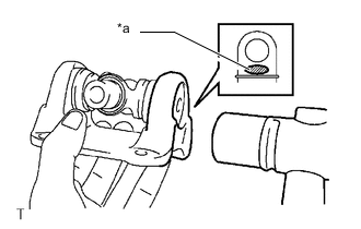
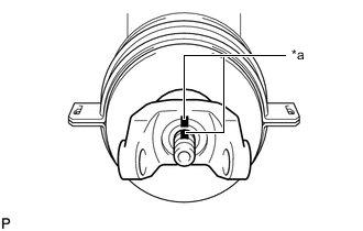
*a Hammering Point Using a hammer, tap the flange yoke until there is no clearance between the spider bearing outer race and snap ring.
Tech Tips
Install the spider bearing on the sleeve side using the procedure described above.
-
Align the matchmarks on the flange yoke and propeller shaft.
-
for 2WD and Pre-Runner:
-
*a Matchmark Align the matchmarks on the center yoke and propeller shaft.
-
*a Matchmark Align the matchmarks on the sleeve yoke and intermediate shaft.
-
-
for 4WD:
-
*a Matchmark Align the matchmarks on the center yoke and sleeve yoke.
-
*a Matchmark Align the matchmarks on the flange yoke and intermediate shaft.
-
-
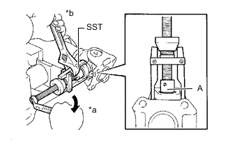
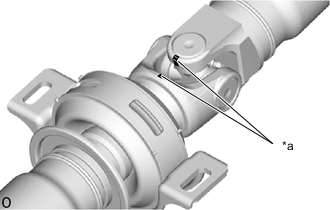
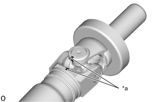
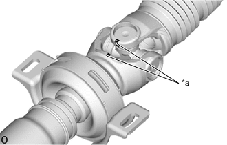
*a Turn *b Hold Using SST, install the 2 spider bearings to the universal joint spider assembly.
- SST
- 09332-25010
Tech Tips
Before installing SST, sufficiently raise the part labeled A. If the part labeled A is too low, it may be difficult to install SST.
-
Using SST, adjust both spider bearings so that the front propeller shaft joint spider bearing snap ring grooves are as wide as possible and equal in width.
- SST
- 09332-25010
-
Install 2 new snap rings to the installed spider bearings. The snap rings must have equal thickness and allow 0 to 0.05 mm (0 to 0.00196 in.) of axial play.
Note
While the installed snap rings should have equal thickness, if the axial play is greater than 0.05 mm (0.00196 in.), select 2 snap rings that have as close to the same thickness as possible.
Tech Tips
Do not reuse the snap rings.
Note
-
While the installed snap rings should have equal thickness, if the axial play is greater than 0.05 mm (0.00196in.), select 2 snap rings that have as close to the same thickness as possible.
-
Use a new snap ring.
-
Use a snap ring with as close to the same thickness as possible on both ends.
Standard Snap Ring Thickness *: For cup with grease nipple.for Vehicle Type A Part No. Color Thickness 90080-52038 Blue 1.638 mm (0.0645 in.) 90080-52039 Yellow 1.588 mm (0.0625 in.) 90080-52040 White 1.537 mm (0.0605 in.) 90080-52041 Black 1.486 mm (0.0585 in.) 90080-52042 Copper 1.511 mm (0.0595 in.) 90080-52156* - -
*: For cup with grease nipple.for Vehicle Type B Part No. Mark Thickness 90521-A0003* Black 1.486 mm (0.0587 in.) 90521-A0005* Yellow 1.588 mm (0.0626 in.) 90521-A0006* Copper 1.512 mm (0.0594 in.) 90521-A0008 Black 1.517 mm (0.0598 in.) 90521-A0010 Blue 1.638 mm (0.0646 in.) 90521-A0011 Black 1.542 mm (0.0606 in.) 90521-A0013 Black 1.618 mm (0.0638 in.) 90521-A0014 Black 1.486 mm (0.0587 in.) 90521-A0015 Copper 1.512 mm (0.0594 in.) 90521-A0016 White 1.556 mm (0.0614 in.)
-
-
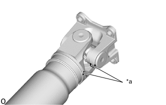
*a Hammering Point Using a hammer, tap the propeller shaft until there is no clearance between the spider bearing outer race and snap ring.
Tech Tips
Install the spider bearing on the sleeve side using the procedure described above.
-
-
INSTALL REAR SLIDING SHAFT BOOT (for 4WD)
-
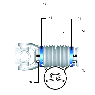
*1 Propeller Shaft Boot Clamp *2 Rear Sliding Shaft Boot *a Matchmark of Propeller Shaft and Sleeve Yoke *b Matchmark of Pinching Portion of Propeller Shaft Boot Clamp *c Pinching Portion Temporarily install a new rear sliding shaft boot to the propeller shaft with 2 new clamps.
-
Coat the splines of the propeller shaft with grease.
Standard Grease Capacity 7.0 to 10.0 g (0.25 to 0.35 oz) -
Align the matchmarks on the propeller shaft and sleeve yoke.
-
Install the sleeve yoke to the propeller shaft and connect the rear sliding shaft boot.
-
Align the matchmarks on the propeller shaft, sleeve yoke and the pinching portions of the 2 rear propeller shaft boot clamps.
Tech Tips
Make sure to align the matchmarks of the propeller shaft boot clamp.
If the pinching portions are installed at different locations than where they were located before disassembly, the rotational balance of the propeller shaft cannot be ensured, which may result in vibrations and noise.
-
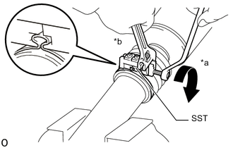
*a Turn *b Hold Secure one of the rear propeller shaft boot clamps to the rear sliding shaft boot.
Tech Tips
-
Use the same procedure for each rear propeller shaft boot clamp.
-
Make sure that the matchmarks of the pinching portion of the rear propeller shaft boot clamp are aligned.
-
Install SST to the rear propeller shaft boot clamp, and then while pressing the rear sliding shaft boot, slightly tighten the SST bolt.
- SST
- 09521-24010
Note
-
Correctly set the rear propeller shaft boot clamp to the guide groove.
-
Do not damage the rear sliding shaft boot.
-
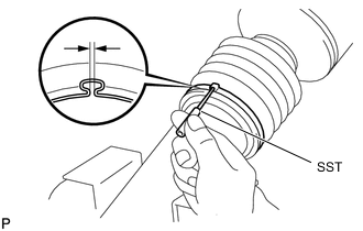
Tighten SST so that the boot clamp is pinched as shown in the illustration.
Standard clearance 3.1 mm (0.122 in.) or less Note
-
When tightening SST, make sure the clearance of the rear propeller shaft boot clamp is within the standard clearance.
-
Do not damage the rear sliding shaft boot.
-
-
Remove SST from the rear propeller shaft boot clamp.
-
Using SST, measure the clearance of the rear propeller shaft boot clamp.
- SST
- 09240-00020
Standard clearance 3.1 mm (0.122 in.) or less Note
If the measured value exceeds the specified value, retighten the rear propeller shaft boot clamp.
-
-
-
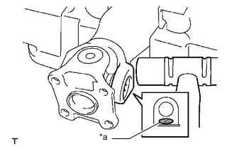
INSPECT PROPELLER SHAFT GREASE FITTING DIRECTION
Tech Tips
-
When replacing a spider bearing, be sure that the grease fitting hole is facing the direction shown in the illustration.
-
Fill the grease fittings with grease.
Grease Lithium base chassis grease NLGI No. 2
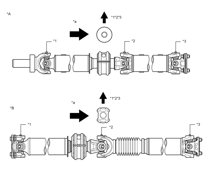
*A for 2WD and Pre-Runner (Vehicle Type B) *B for 4WD *1 No. 1 Grease Fitting *2 No. 2 Grease Fitting *3 No. 3 Grease Fitting - - *a Rear Side - - -
-
INSPECT SPIDER BEARING