FRONT PROPELLER SHAFT ASSEMBLY(for TMT Made) REASSEMBLY

CAUTION / NOTICE / HINT
Note
-
When using a vise, place aluminum plates between the part and vise.
-
When using a vise, do not overtighten it.
PROCEDURE
-
INSTALL SPIDER BEARING
Tech Tips
Use the same procedure for both spiders.
-
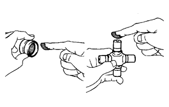
Apply grease to a new spider and new spider bearings.
Grease Lithium base chassis grease NLGI No. 2 Note
Do not apply too much grease.
-
Install the spider to the flange yoke.
-
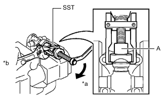
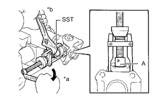
*a Turn *b Hold Using SST, install 2 of the spider bearings to the spider.
- SST
- 09332-25010
Tech Tips
Before installing SST, sufficiently raise the part labeled A. If the part labeled A is too low, it may be difficult to install SST.
-
Using SST, adjust both spider bearings so that the snap ring grooves are as wide as possible and equal in width.
- SST
- 09332-25010
-
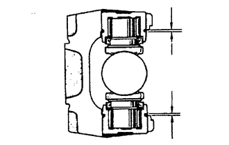
Install 2 new snap rings to the installed spider bearings. The snap rings must have equal thickness and allow 0 to 0.05 mm (0 to 0.00196 in.) of axial play.
Note
While the installed snap rings should have equal thickness, if the axial play is greater than 0.05 mm (0.00196 in.), select 2 snap rings that have as close to the same thickness as possible.
Tech Tips
Do not reuse the snap rings.
Standard Snap Ring Thickness Part No. Mark Thickness 90520-T0007 F 2.18 to 2.20 mm (0.0859 to 0.0866 in.) 90520-T0008 G 2.20 to 2.22 mm (0.0867 to 0.0874 in.) 90520-T0009 H 2.22 to 2.24 mm (0.0875 to 0.0881 in.) 90520-T0010 J 2.24 to 2.26 mm (0.0882 to 0.0889 in.) 90520-T0011 K 2.26 to 2.28 mm (0.0890 to 0.0897 in.) 90520-T0012 1 2.28 to 2.30 mm (0.0898 to 0.0905 in.) 90520-T0013 2 2.30 to 2.32 mm (0.0906 to 0.0913 in.) 90520-T0014 3 2.32 to 2.34 mm (0.0914 to 0.0921 in.) 90520-T0015 4 2.34 to 2.36 mm (0.0922 to 0.0929 in.) 90520-T0016 5 2.36 to 2.38 mm (0.0930 to 0.0937 in.) 90520-T0017 6 2.38 to 2.40 mm (0.0938 to 0.0944 in.) 90520-T0018 7 2.40 to 2.42 mm (0.0945 to 0.0952 in.) 90520-T0019 8 2.42 to 2.44 mm (0.0953 to 0.0960 in.) 90520-T0020 N 2.44 to 2.46 mm (0.0961 to 0.0968 in.) 90520-T0021 10 2.46 to 2.48 mm (0.0969 to 0.0976 in.) 90520-T0022 A 2.48 to 2.50 mm (0.0977 to 0.0984 in.) 90520-T0023 B 2.50 to 2.52 mm (0.0985 to 0.0992 in.) 90520-T0024 C 2.52 to 2.54 mm (0.0993 to 0.0999 in.) 90520-T0025 D 2.54 to 2.56 mm (0.1000 to 0.1007 in.) 90520-T0026 E 2.56 to 2.58 mm (0.1008 to 0.1015 in.) Note
-
Use a new snap ring.
-
Use a snap ring with as close to the same thickness as possible on both ends.
-
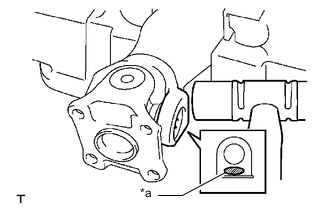
-
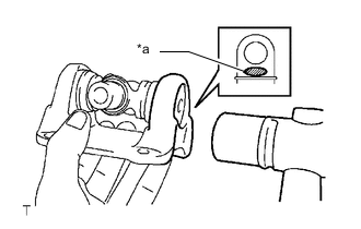
*a Hammering Point Using a hammer, tap the flange yoke until there is no clearance between the spider bearing outer race and snap ring.
Tech Tips
Install the spider bearing on the sleeve side using the procedure described above.
-
Align the matchmarks on the flange yoke and propeller shaft.
-
*a Turn *b Hold Using SST, install the 2 spider bearings to the spider.
- SST
- 09332-25010
Tech Tips
Before installing SST, sufficiently raise the part labeled A. If the part labeled A is too low, it may be difficult to install SST.
-
Using SST, adjust both spider bearings so that the snap ring grooves are as wide as possible and equal in width.
- SST
- 09332-25010
-
Install 2 new snap rings to the installed spider bearings. The snap rings must have equal thickness and allow 0 to 0.05 mm (0 to 0.00196 in.) of axial play.
Note
While the installed snap rings should have equal thickness, if the axial play is greater than 0.05 mm (0.00196 in.), select 2 snap rings that have as close to the same thickness as possible.
Tech Tips
Do not reuse the snap rings.
Standard Snap Ring Thickness Part No. Mark Thickness 90520-T0007 F 2.18 to 2.20 mm (0.0859 to 0.0866 in.) 90520-T0008 G 2.20 to 2.22 mm (0.0867 to 0.0874 in.) 90520-T0009 H 2.22 to 2.24 mm (0.0875 to 0.0881 in.) 90520-T0010 J 2.24 to 2.26 mm (0.0882 to 0.0889 in.) 90520-T0011 K 2.26 to 2.28 mm (0.0890 to 0.0897 in.) 90520-T0012 1 2.28 to 2.30 mm (0.0898 to 0.0905 in.) 90520-T0013 2 2.30 to 2.32 mm (0.0906 to 0.0913 in.) 90520-T0014 3 2.32 to 2.34 mm (0.0914 to 0.0921 in.) 90520-T0015 4 2.34 to 2.36 mm (0.0922 to 0.0929 in.) 90520-T0016 5 2.36 to 2.38 mm (0.0930 to 0.0937 in.) 90520-T0017 6 2.38 to 2.40 mm (0.0938 to 0.0944 in.) 90520-T0018 7 2.40 to 2.42 mm (0.0945 to 0.0952 in.) 90520-T0019 8 2.42 to 2.44 mm (0.0953 to 0.0960 in.) 90520-T0020 N 2.44 to 2.46 mm (0.0961 to 0.0968 in.) 90520-T0021 10 2.46 to 2.48 mm (0.0969 to 0.0976 in.) 90520-T0022 A 2.48 to 2.50 mm (0.0977 to 0.0984 in.) 90520-T0023 B 2.50 to 2.52 mm (0.0985 to 0.0992 in.) 90520-T0024 C 2.52 to 2.54 mm (0.0993 to 0.0999 in.) 90520-T0025 D 2.54 to 2.56 mm (0.1000 to 0.1007 in.) 90520-T0026 E 2.56 to 2.58 mm (0.1008 to 0.1015 in.) Note
-
Use a new snap ring.
-
Use snap rings with as close to the same thickness as possible on both ends.
-
-
*a Hammering Point Using a hammer, tap the propeller shaft until there is no clearance between the spider bearing outer race and snap ring.
Tech Tips
Install the spider bearing on the sleeve side using the procedure described above.
-
-
INSPECT PROPELLER SHAFT GREASE FITTING DIRECTION
Tech Tips
-
When replacing a spider bearing, be sure that the grease fitting hole is facing the direction shown in the illustration.
-
Fill the grease fittings with grease.
Grease Lithium base chassis grease NLGI No. 2
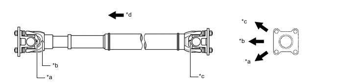
*a No. 1 Grease Fitting *b No. 2 Grease Fitting *c No. 3 Grease Fitting *d Rear Side -
-
INSPECT SPIDER BEARING