FRONT PROPELLER SHAFT ASSEMBLY(for TSAM Made) INSTALLATION

PROCEDURE
-
INSTALL FRONT PROPELLER SHAFT ASSEMBLY
Note
Refer to the components illustration for the installation direction of the front propeller shaft assembly.
-
Completely remove any oil, etc. and clean the contact surfaces of the 2 propeller shaft flanges, differential flange and transfer flange.
-
Align the matchmarks on the propeller shaft flange and differential flange.
-
Install the front propeller shaft assembly with the 4 nuts, 4 bolts and 4 washers.
- Torque:
- 88.2 N*m { 899 kgf*cm, 65 ft.*lbf }
-
Align the matchmarks on the propeller shaft flange and transfer flange.
-
Install the front propeller shaft assembly with the 4 washers and 4 nuts.
- Torque:
- 88.2 N*m { 899 kgf*cm, 65 ft.*lbf }
-
-
INSTALL PROPELLER SHAFT GUARD
-
Install the propeller shaft guard bracket LH.
Tech Tips
Perform this procedure only when replacement of the propeller shaft guard bracket LH is necessary.
-
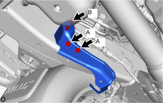
w/ Urea SCR System:
Install the propeller shaft guard bracket LH with the 2 bolts (A).
- Torque:
- 30 N*m { 306 kgf*cm, 22 ft.*lbf }
-
w/ Urea SCR System:
Temporarily install bolt (B).
-
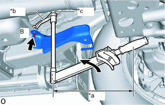
*a Torque Wrench Fulcrum Length *b 12 x 14 mm Short Offset Wrench *c Straight Hexagon Wrench 14 w/ Urea SCR System:
Using a straight hexagon wrench 14 and 12 x 14 mm short offset wrench, tighten bolt (B).
- Torque:
- Specified tightening torque
- 14.3 N*m { 146 kgf*cm, 11 ft.*lbf }
Tech Tips
-
Calculate the torque wrench reading when changing the fulcrum length of the torque wrench.
-
When using a short offset wrench (fulcrum length of 125.25 mm (4.931 in.)) + torque wrench (fulcrum length of 300 mm (11.811 in.)): 10.1 N*m (103 kgf*cm, 7 ft.*lbf)
-
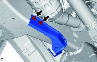
w/o Urea SCR System:
Install the propeller shaft guard bracket LH with the 2 bolts.
- Torque:
- 30 N*m { 306 kgf*cm, 22 ft.*lbf }
-
-
Install the propeller shaft guard bracket RH with the 2 bolts.
- Torque:
- 30 N*m { 306 kgf*cm, 22 ft.*lbf }
Tech Tips
Perform this procedure only when replacement of the propeller shaft guard bracket RH is necessary.
-
Install the front propeller shaft guard with the 2 bolts.
- Torque:
- 36.2 N*m { 369 kgf*cm, 27 ft.*lbf }
-
-
INSTALL NO.3 ENGINE UNDER COVER (w/ Cover)
- Torque:
- 28 N*m { 286 kgf*cm, 21 ft.*lbf }