FRONT DRIVE SHAFT ASSEMBLY INSTALLATION

CAUTION / NOTICE / HINT
Tech Tips
-
Use the same procedure for the RH and LH sides.
-
The procedure listed below is for the LH side.
PROCEDURE
-
INSTALL FRONT DRIVE SHAFT HOLE SNAP RING
-
Install a new front drive shaft hole snap ring.
Note
-
Do not damage the spline of the inboard joint.
-
The front drive shaft hole snap ring should be installed completely.
-
-
-
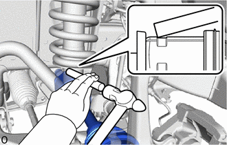
INSTALL FRONT DRIVE SHAFT ASSEMBLY LH
-
Coat the splines of the inboard joint with differential oil.
-
Coat the snap ring of the inboard joint with MP grease.
-
Align the splines and tap in the front drive shaft assembly LH with a brass bar and hammer.
Note
-
Using MP grease, set the front drive shaft hole snap ring in the groove with the opening facing downwards and centered radially.
-
Do not damage the inboard joint boot, front drive shaft dust cover LH and differential side gear shaft oil seal.
-
Make sure to follow the proper handling and installation procedures. If the front drive shaft assembly LH is installed at too large an angle or slides too much, it may fall out of the groove of the tripod joint.
-
Do not tap the end of the front drive outboard joint assembly with a hammer, etc.
Tech Tips
Determine whether the front drive shaft assembly LH is completely tapped in by checking for changes in the tapping sound or the reaction of the brass bar.
-
-
-
CONNECT FRONT SPEED SENSOR
-
CONNECT FRONT LOWER SUSPENSION ARM ASSEMBLY LH
-
CONNECT TIE ROD END SUB-ASSEMBLY LH
-
INSTALL FRONT AXLE SHAFT NUT
-
INSTALL FRONT AXLE HUB GREASE CAP
-
INSTALL FRONT WHEEL
-
ADD DIFFERENTIAL OIL
-
INSTALL NO. 2 ENGINE UNDER COVER
- Torque:
- 28 N*m { 286 kgf*cm, 21 ft.*lbf }
-
INSTALL NO. 1 ENGINE UNDER COVER
- Torque:
- for M6 bolt
- 11.5 N*m { 117 kgf*cm, 8 ft.*lbf }
- for M8 bolt
- 28 N*m { 286 kgf*cm, 21 ft.*lbf }
-
CHECK ABS SPEED SENSOR SIGNAL
-
w/ VSC: Click here
-
w/o VSC: Click here
-
-
INSPECT AND ADJUST FRONT WHEEL ALIGNMENT
-
PERFORM INITIALIZATION (w/ Automatic Headlight Beam Level Control System)
-
INSPECT AUTOMATIC LIGHT CONTROL SYSTEM (w/ Automatic Headlight Beam Level Control System)
-
INSPECT HEADLIGHT AIMING (w/ Automatic Headlight Beam Level Control System)