PROCEDURE
- Click here
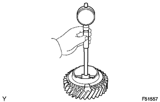
INSPECT COUNTER GEAR
-
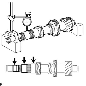
Using a dial indicator and 2 V-blocks, measure the counter gear runout.
Maximum runout 0.03 mm (0.00118 in.) If the runout is more than the maximum, replace the counter gear.
Tip:Measure the 3 areas shown in the illustration with the counter gear level.
-
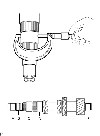
Using a micrometer, measure the journal diameter of each counter gear journal, at the specified positions.
Standard Journal Diameter Item Specified Condition Journal A 35.002 to 35.015 mm (1.3781 to 1.3785 in.) Journal B 36.985 to 37.000 mm (1.4561 to 1.4566 in.) Journal C 47.985 to 48.000 mm (1.8892 to 1.8897 in.) Journal D 53.985 to 54.000 mm (2.1254 to 2.1259 in.) Journal E 34.002 to 34.015 mm (1.3387 to 1.3391 in.) Minimum Journal Diameter Item Specified Condition Journal A 35.002 mm (1.3781 in.) Journal B 36.985 mm (1.4561 in.) Journal C 47.985 mm (1.8892 in.) Journal D 53.985 mm (2.1254 in.) Journal E 34.002 mm (1.3387 in.) If the journal diameter is less than the minimum, replace the counter gear.
-
- Click here
INSPECT COUNTERSHAFT REVERSE GEAR
-
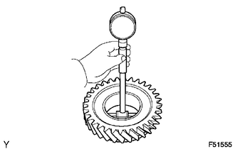
Using a cylinder gauge, measure the inside diameter of the countershaft reverse gear.
Standard inside diameter 51.015 to 51.040 mm (2.0085 to 2.0094 in.) Maximum inside diameter 51.040 mm (2.0094 in.) If the inside diameter is more than the maximum, replace the countershaft reverse gear.
-
- Click here
INSPECT COUNTERSHAFT 1ST SPEED GEAR
-
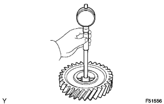
Using a cylinder gauge, measure the inside diameter of the countershaft 1st speed gear.
Standard inside diameter 54.015 to 54.040 mm (2.1266 to 2.1275 in.) Maximum inside diameter 54.040 mm (2.1275 in.) If the inside diameter is more than the maximum, replace the countershaft 1st speed gear.
-
- Click here
INSPECT COUNTERSHAFT 2ND SPEED GEAR
-
Using a cylinder gauge, measure the inside diameter of the countershaft 2nd speed gear.
Standard inside diameter 60.015 to 60.040 mm (2.3628 to 2.3637 in.) Maximum inside diameter 60.040 mm (2.3637 in.) If the inside diameter is more than the maximum, replace the countershaft 2nd speed gear.
-
- Click here
INSPECT NO. 4 TRANSMISSION HUB SLEEVE
-
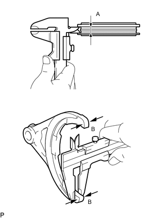
Using a vernier caliper, measure the width of the No. 4 transmission hub sleeve groove (A) and the thickness of the 2 claw parts of the No. 4 gear shift fork (B), and calculate the clearance.
Standard clearance (A - B) 0.30 to 0.50 mm (0.012 to 0.019 in.) If the clearance is outside the specification, replace the No. 4 transmission hub sleeve and No. 4 gear shift fork.
-
- Click here
INSPECT NO. 1 TRANSMISSION HUB SLEEVE
-
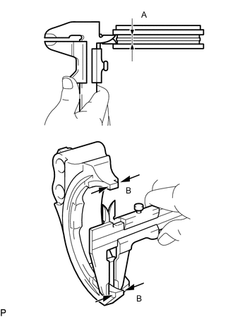
Using a vernier caliper, measure the width of the No. 1 transmission hub sleeve groove (A) and the thickness of the 2 claw parts of the No. 1 gear shift fork (B), and calculate the clearance.
Standard clearance (A - B) 0.15 to 0.35 mm (0.006 to 0.013 in.) If the clearance is outside the specification, replace the No. 1 transmission hub sleeve and No. 1 gear shift fork.
-
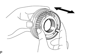
Check the sliding condition between the No. 1 transmission clutch hub and No. 1 transmission hub sleeve.
-
Check that the splines of the No. 1 transmission hub sleeve are not worn.
-
- Click here
INSPECT NO. 1 SYNCHRONIZER RING SET
-
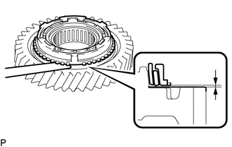
Using a feeler gauge, measure the clearance between the No. 1 synchronizer ring set and countershaft 1st speed gear.
Standard clearance 0.83 to 1.77 mm (0.0327 to 0.0696 in.) Minimum clearance 0.83 mm (0.0326 in.) If the clearance is less than the minimum, replace the No. 1 synchronizer ring set.
-
Coat the countershaft 1st speed gear cone with gear oil.
-
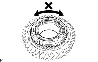
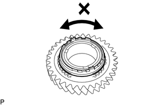
Check the braking effect of the synchronizer ring.
-
Turn the synchronizer ring in both directions while pushing it against the countershaft 1st speed gear cone. Check that the ring locks in both directions. If the No. 1 synchronizer ring set turns, replace it.
-
-
- Click here
INSPECT NO. 2 SYNCHRONIZER RING SET
-
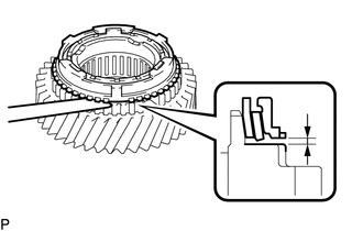
Using a feeler gauge, measure the clearance between the No. 2 synchronizer ring set and countershaft 2nd speed gear.
Standard clearance 0.88 to 1.72 mm (0.0347 to 0.0677 in.) Minimum clearance 0.88 mm (0.0347 in.) If the clearance is less than the minimum, replace the No. 2 synchronizer ring set.
-
Coat the countershaft 2nd speed gear cone with gear oil.
-
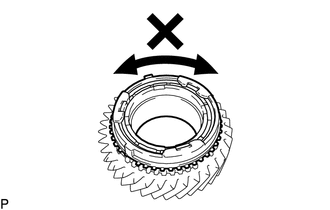
Check the braking effect of the No. 2 synchronizer ring set.
-
Turn the synchronizer ring in both directions while pushing it against the countershaft 2nd speed gear cone. Check that the ring locks in both directions. If the No. 2 synchronizer ring set turns, replace it.
-
-
- Click here
INSPECT REVERSE SYNCHRONIZER RING
-

Using a feeler gauge, measure the clearance between the reverse synchronizer ring and countershaft 2nd speed gear.
Standard clearance 0.65 to 1.35 mm (0.0256 to 0.0531 in.) Minimum clearance 0.65 mm (0.0256 in.) If the clearance is less than the minimum, replace the reverse synchronizer ring.
-
Check the braking effect of the reverse synchronizer ring.
-
Turn the synchronizer ring in both directions while pushing it against the countershaft reverse gear cone. Check that the ring locks in both directions. If the reverse synchronizer ring turns, replace it.
-
-