MANUAL TRANSMISSION SYSTEM TERMINALS OF ECM
-
ECM
Tech Tips
The standard voltage and resistance of each ECM terminal is shown in the table below.
In the table, first follow the information under "Condition". Look under "Terminal No. (Symbol)" for the terminals to be inspected. The standard voltage or resistance between the terminals is shown under "Specified Condition".
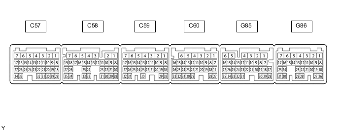
Use the illustration above as a reference for the ECM terminals.
Terminal No. (Symbol) Wiring Color Terminal Description Condition Specified Condition C59-12 (NIMB) - C60-1 (E1) B - W-B Power supply for transmission revolution sensor Ignition switch ON 11 to 14 V C59-13 (NIMO) - C60-1 (E1) W - W-B Transmission revolution sensor signal Engine idling and clutch pedal fully released Pulse generation G85-8 (MTMS) - C60-1 (E1) B - W-B iMT switch signal Ignition switch ON and iMT switch pushed Below 1.5 V Ignition switch ON and iMT switch not pushed 11 to 14 V G85-17 (CANH) - C60-1 (E1) B - W-B CAN communication line Ignition switch ON Pulse generation G85-28 (CANL) - C60-1 (E1) W - W-B CAN communication line Ignition switch ON Pulse generation G86-20 (CLS) - G86-21 (E2CL) SB - R Clutch stroke sensor signal Ignition switch ON and clutch pedal fully released 0.2 to 1.5 V Ignition switch ON and clutch pedal fully depressed 2.5 to 4.8 V G86-23 (VCCL) - C60-1 (E1) G - W-B Power supply for clutch stroke sensor Ignition switch ON 4.5 to 5.5 V