CLUTCH UNIT(for RC60, RC61) INSTALLATION

PROCEDURE
-
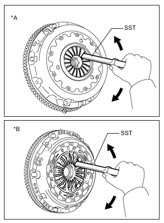
INSTALL CLUTCH DISC ASSEMBLY
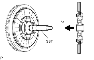
*a Flywheel Side
-
Insert SST into the clutch disc assembly. Then insert SST (together with the clutch disc) into the flywheel.
- SST
- 09301-00110
Note
Be sure to install the clutch disc so that it is facing in the correct direction.
-
-
INSTALL CLUTCH COVER ASSEMBLY (for GD Series Engine)
-
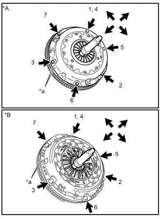
*a Matchmark *A except Luk made *B for Luk made Align the matchmarks on the clutch cover assembly and flywheel.
Note
Make sure to use a Luk clutch disc and clutch cover with the same matching numbers as shown at the position indicated by the arrow in the illustration.
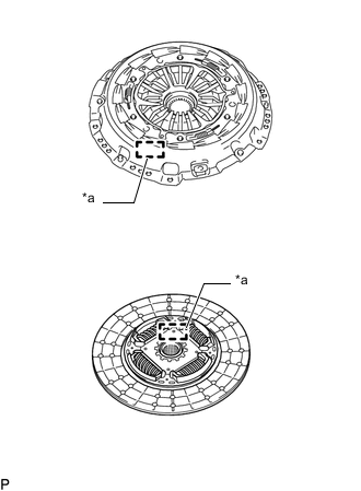
*a Matching Number -
Tighten the 6 bolts as described below.
-
In the order shown in the illustration, temporarily install the 6 bolts starting from the bolt located near the knock pin on the top
-
-
Lightly move SST up and down, and right and left.
- SST
- 09301-00110
-
Check that the disc is in the center, and then tighten the bolts.
- Torque:
- 19.1 N*m { 195 kgf*cm, 14 ft.*lbf }
-
-
INSPECT AND ADJUST CLUTCH COVER ASSEMBLY (for GD Series Engine)
-
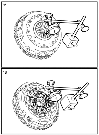
*A except Luk made *B for Luk made Using a dial indicator with a roller instrument, measure the diaphragm spring tip alignment.
Maximum misalignment 0.5 mm (0.020 in.)
-
*A except Luk made *B for Luk made If the misalignment is more than the maximum, use SST to adjust the diaphragm spring tip alignment.
- SST
- 09333-00013
-
-
-
INSTALL RELEASE FORK SUPPORT
-
Install the release fork support to the manual transmission unit.
- Torque:
- 49 N*m { 500 kgf*cm, 36 ft.*lbf }
-
-
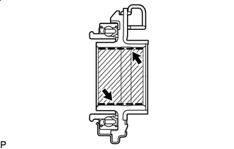
INSTALL CLUTCH RELEASE FORK DUST SEAL
-
Install the clutch release fork dust seal to the clutch release fork sub-assembly.
-
Install the clutch release fork collar to the clutch release fork sub-assembly.
-
-
INSTALL CLUTCH RELEASE BEARING ASSEMBLY
-

Multemp 8158 grease or equivalent Apply grease to the clutch release bearing assembly.
Grease Multemp 8158 grease or equivalent Amount of Grease 0.3 to 0.5 g (0.011 to 0.018 oz) Tech Tips
When replacing the clutch release bearing assembly with a new one, do not apply grease.
-
Install the release bearing hub clip to the clutch release bearing assembly.
-
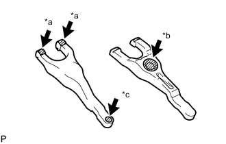
*a The surfaces of the release fork that contact the release bearing *b The surfaces of the release fork that contact the release fork support *c The surfaces of the release fork that contact the push rod of the release cylinder Multemp 8158 grease or equivalent Apply grease or equivalent to the following areas.
Grease Multemp 8158 grease or equivalent Amount of Grease The surfaces of the release fork that contact the release bearing 1.0 to 1.3 g (0.04 to 0.05 oz) The surfaces of the release fork that contact the release fork support 1.3 to 1.8 g (0.05 to 0.06 oz) The surfaces of the release fork that contact the push rod of the release cylinder 0.5 to 0.9 g (0.02 to 0.03 oz) -
Install the release fork sub-assembly to the clutch release bearing assembly.
-
Install the clutch release bearing assembly together with the clutch release fork sub-assembly to the clutch housing.
Note
After the installation, move the fork forward and backward to check that the release bearing slides smoothly.
-
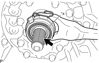
*a Contact surface of the bearing Toyota Genuine Clutch Spline Grease or equivalent Apply the clutch spline grease to the spline of the input shaft.
Grease Toyota Genuine Clutch Spline Grease or equivalent Note
Make sure that no grease adheres to the contact surface of the bearing.
-
-
INSTALL CLUTCH RELEASE FORK BOOT
-
INSTALL MANUAL TRANSMISSION UNIT ASSEMBLY
RC60 / RC61: Click here
RC60F / RC61F: Click here