PROCEDURE
- Click here
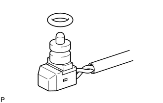
REMOVE BREATHER PLUG HOSE
-
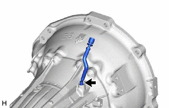
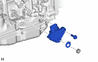
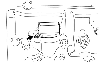
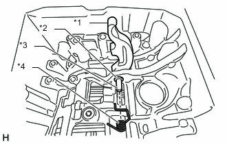
Remove the bolt and breather plug hose from the automatic transmission case sub-assembly.
-
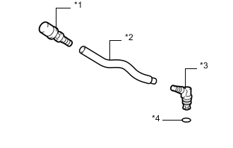
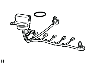
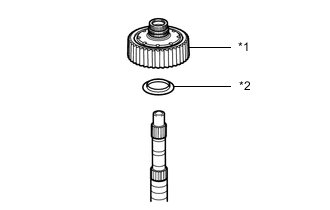
*1 Breather Plug Sub-assembly *2 Breather Plug Hose *3 Breather Plug *4 O-ring Remove the O-ring from the breather plug.
-
Remove the breather plug sub-assembly and breather plug from the breather plug hose.
-
- Click here
REMOVE TRANSMISSION REVOLUTION SENSOR
-
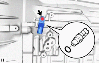
Remove the bolt and transmission revolution sensor (NT) from the automatic transmission case sub-assembly.
-
Remove the O-ring from the transmission revolution sensor (NT).
-
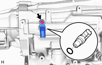
Remove the bolt and transmission revolution sensor (SP2) from the automatic transmission case sub-assembly.
-
Remove the O-ring from the transmission revolution sensor (SP2).
-
- Click here
REMOVE TRANSMISSION CONTROL SHAFT LEVER LH
-
Remove the nut, spring washer and transmission control shaft lever LH from the manual valve lever shaft.
-
- Click here
REMOVE PARK/NEUTRAL POSITION SWITCH ASSEMBLY
-
Using a screwdriver, bend the tabs of the lock washer.
-
Remove the nut and lock washer.
-
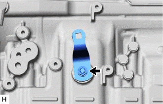
Remove the bolt and park/neutral position switch assembly from the automatic transmission case sub-assembly.
Tip:Make sure that the manual valve lever shaft has not been rotated prior to installing the park/neutral position switch assembly as the detent spring may become detached from the manual valve lever shaft.
-
- Click here
REMOVE REFILL PLUG
-
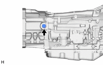
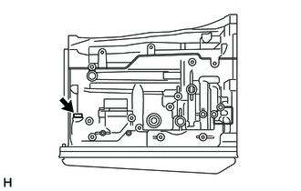
Remove the refill plug from the transfer adaptor sub-assembly.
-
Remove the O-ring from the refill plug.
-
- Click here
REMOVE AUTOMATIC TRANSMISSION CASE PLUG
-
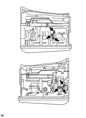
Remove the 6 automatic transmission case plugs from the automatic transmission case sub-assembly.
-
Remove the 6 O-rings from the 6 automatic transmission case plugs.
-
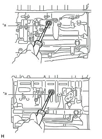
Using a T55 "TORX" socket wrench, remove the automatic transmission case plug from the automatic transmission case sub-assembly.
-
Remove the O-ring from the automatic transmission case plug.
-
- Click here
REMOVE OIL COOLER TUBE UNION
-
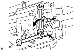
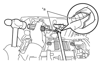
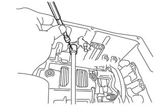
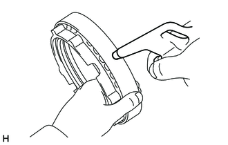
*a Turn *b Hold Remove the 2 oil cooler tube unions from the automatic transmission case sub-assembly.
-
Remove the 2 O-rings from the 2 oil cooler tube unions.
-
- Click here
REMOVE TRANSFER ADAPTER SUB-ASSEMBLY
-
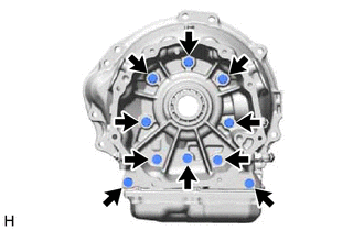
Remove the 10 bolts and transfer adapter sub-assembly from the automatic transmission case sub-assembly.
Tip:Use a brass bar and hammer to remove the extension housing.
-
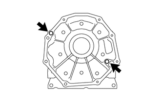
Remove the 2 straight pins from the transfer adapter sub-assembly.
Tip:It is not necessary to remove the straight pins they are being replaced.
-
- Click here
REMOVE TRANSFER ADAPTER OIL SEAL
-
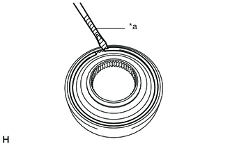
*a Protective Tape Using a screwdriver, pry out the transfer adapter oil seal from the transfer adapter sub-assembly.
Note:Be careful not to damage the transfer adapter sub-assembly.
Tip:Tape the screwdriver tip before use.
-
- Click here
REMOVE REAR TRANSFER CASE ADAPTER OIL RECEIVER
-
Using snap ring pliers, remove the snap ring and rear transfer case adapter oil receiver from the transfer adapter sub-assembly.
-
- Click here
REMOVE AUTOMATIC TRANSMISSION HOUSING
-
Remove the 12 bolts and automatic transmission housing from the automatic transmission case sub-assembly.
-
- Click here
SECURE AUTOMATIC TRANSMISSION CASE SUB-ASSEMBLY
-
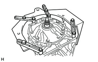
Install the automatic transmission case sub-assembly to an overhaul attachment.
-
- Click here
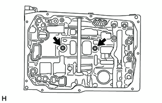
REMOVE AUTOMATIC TRANSMISSION OIL PAN SUB-ASSEMBLY
Note:Do not turn the transmission over as this will contaminate the transmission valve body assembly with foreign matter located at the bottom of the automatic transmission oil pan sub-assembly.
-
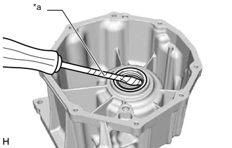
Using a 5 mm socket hexagon wrench, remove the overflow plug and gasket.
-
Remove the drain plug and gasket.
-
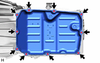
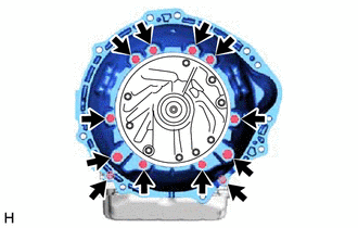
Remove the 10 bolts, automatic transmission oil pan sub-assembly and automatic transmission oil pan gasket.
-
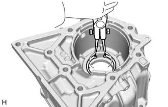
Remove the 4 transmission oil cleaner magnets from the automatic transmission oil pan sub-assembly.
-
Examine the particles in the automatic transmission oil pan sub-assembly.
-
Collect any steel chips with the removed transmission oil cleaner magnets. Carefully inspect the foreign matter and particles in the automatic transmission oil pan sub-assembly and on the transmission oil cleaner magnets to anticipate the type of wear you will find in the automatic transmission assembly.
Steel (magnetic): bearing, gear and clutch plate wear
Brass (non-magnetic): bush wear
-
-
- Click here
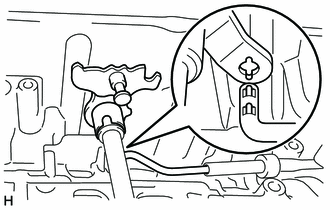
REMOVE TRANSMISSION WIRE
-
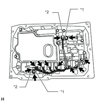
*1 Temperature Sensor Clamp *2 Temperature Sensor Remove the 2 bolts and 2 temperature sensor clamps, and disconnect the 2 temperature sensors.
-
Disconnect the 7 solenoid valve connectors and transmission wire from the transmission valve body assembly.
-
Remove the bolt and pull out the transmission wire from the automatic transmission case sub-assembly.
-
Remove the O-ring from the connector of transmission wire.
-
Remove the 2 O-rings from the 2 temperature sensors.
-
- Click here
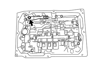
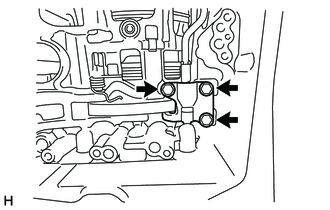
REMOVE VALVE BODY OIL STRAINER ASSEMBLY
-
Remove the 3 bolts and valve body oil strainer assembly from the transmission valve body assembly.
-
Remove the O-ring from the valve body oil strainer assembly.
-
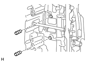
- Click here
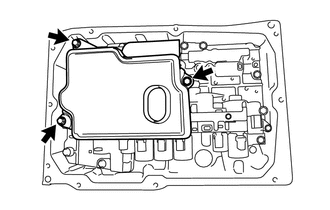
REMOVE TRANSMISSION VALVE BODY ASSEMBLY
-
Remove the bolt, detent spring cover and detent spring from the transmission valve body assembly.
-
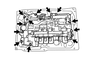
Remove the 12 bolts and transmission valve body assembly from the automatic transmission case sub-assembly.
-
- Click here
REMOVE TRANSMISSION CASE GASKET
-
Remove the 2 transmission case gaskets from the automatic transmission case sub-assembly.
-
- Click here
REMOVE BRAKE DRUM GASKET
-
Remove the 2 brake drum gaskets from the automatic transmission case sub-assembly.
-
- Click here
REMOVE PARKING LOCK PAWL BRACKET
-
Remove the 3 bolts and parking lock pawl bracket from the automatic transmission case sub-assembly.
-
- Click here
REMOVE PARKING LOCK ROD SUB-ASSEMBLY
-
Remove the parking lock rod sub-assembly from the manual valve lever sub-assembly.
-
- Click here
REMOVE PARKING LOCK PAWL SHAFT
-
*1 Parking Lock Pawl *2 E-ring *3 Parking Lock Pawl Shaft *4 Spring Pull out the parking lock pawl shaft from the front side, and remove the parking lock pawl and spring.
-
Remove the E-ring from the parking lock pawl shaft.
-
- Click here
REMOVE MANUAL VALVE LEVER SUB-ASSEMBLY
-
*a Protective Tape Using a screwdriver and hammer, cut off the spacer and remove it from the manual valve lever shaft.
Note:Be careful not to damage the manual valve lever shaft.
Tip:Tape the screwdriver tip before use.
-
Using a 3 mm pin punch and hammer, drive out the spring pin.
Tip:Slowly drive out the spring pin so that it does not fall into the automatic transmission case sub-assembly.
-
Pull the manual valve lever shaft out through the case and remove the manual valve lever sub-assembly.
-
- Click here
REMOVE MANUAL VALVE LEVER SHAFT OIL SEAL
-
*a Protective Tape Using a screwdriver, pry out the 2 manual valve lever shaft oil seals from the automatic transmission case sub-assembly.
Note:Be careful not to damage the automatic transmission case sub-assembly.
Tip:Tape the screwdriver tip before use.
-
- Click here
REMOVE OIL PUMP ASSEMBLY
-
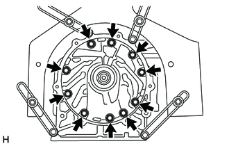
Remove the 10 bolts.
-
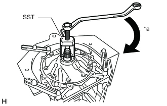
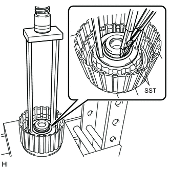
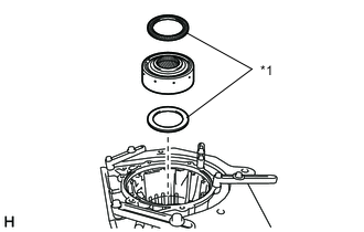
*a Turn Using SST, pull out the oil pump assembly from the automatic transmission case sub-assembly.
09610-20012 -
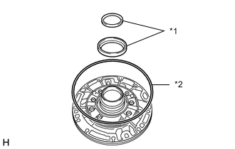
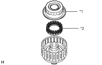
*1 Thrust Bearing Race *2 Oil Pump O-ring Remove the 2 thrust bearing races from the oil pump assembly.
-
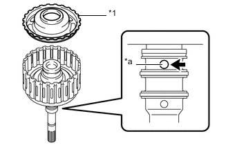
Remove the oil pump O-ring from the oil pump assembly.
-
- Click here
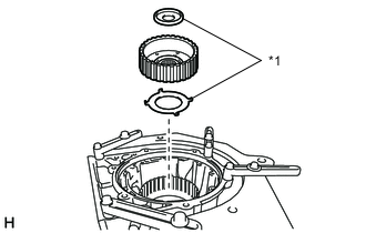
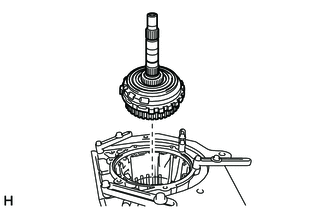
REMOVE CLUTCH DRUM AND INPUT SHAFT ASSEMBLY
-
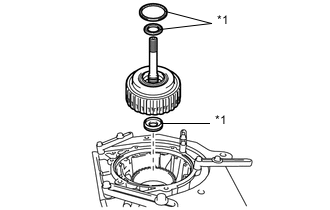
*1 Thrust Needle Roller Bearing Remove the clutch drum and input shaft assembly from the automatic transmission case sub-assembly.
-
Remove the 3 thrust needle roller bearings from the clutch drum and input shaft assembly.
-
- Click here
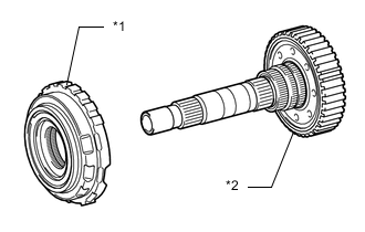
REMOVE DIRECT CLUTCH DRUM SUB-ASSEMBLY
-
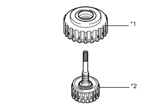
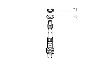
*1 Direct Clutch Drum Sub-assembly *2 Input Shaft Sub-assembly Remove the direct clutch drum sub-assembly from the input shaft sub-assembly.
-
- Click here
INSPECT CLEARANCE OF NO. 1 CLUTCH (FORWARD CLUTCH)
- Click here
REMOVE CLUTCH DRUM OIL SEAL RING
-
Remove the 3 clutch drum oil seal rings from the input shaft sub-assembly.
-
- Click here
REMOVE NO. 1 CLUTCH DISC (FORWARD CLUTCH DISC)
-
Secure the input shaft sub-assembly in a vise between aluminum plates.
Note:Do not overtighten the vise.
-
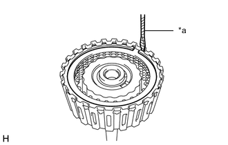
*a Protective Tape Using a screwdriver, remove the snap ring.
Note:Be careful not to damage the input shaft sub-assembly.
Tip:Tape the screwdriver tip before use.
-
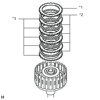
*1 Forward Clutch Flange *2 No. 1 Clutch Disc *3 No. 1 Clutch Plate Remove the forward clutch flange, 5 No. 1 clutch discs and 5 No. 1 clutch plates from the input shaft sub-assembly.
-
- Click here
INSPECT NO. 1 CLUTCH DISC (FORWARD CLUTCH DISC)
- Click here
REMOVE NO. 1 CLUTCH BALANCER
-
Place SST on the No. 1 clutch balancer, and compress the forward clutch return spring sub-assembly with a press.
09387-00110 -
Using SST, remove the snap ring.
09350-30020 09350-07070 -
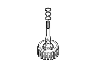
*1 No. 1 Clutch Balancer *2 Forward Clutch Return Spring Sub-assembly Remove the No. 1 clutch balancer and forward clutch return spring sub-assembly from the input shaft sub-assembly.
-
Remove the O-ring from the No. 1 clutch balancer.
-
- Click here
INSPECT FORWARD CLUTCH RETURN SPRING SUB-ASSEMBLY
- Click here
REMOVE FORWARD CLUTCH PISTON
-
*1 Forward Clutch Piston *a Oil Hole While holding the forward clutch piston, apply compressed air to the oil hole of the input shaft sub-assembly to remove the forward clutch piston from the input shaft sub-assembly.
-
Remove the O-ring from the forward clutch piston.
-
Remove the O-ring from the input shaft sub-assembly.
-
- Click here
INSPECT INPUT SHAFT SUB-ASSEMBLY
- Click here
INSPECT CLEARANCE OF NO. 2 CLUTCH (DIRECT CLUTCH)
- Click here
REMOVE NO. 2 CLUTCH DISC (DIRECT CLUTCH DISC)
-
*a Protective Tape Using a screwdriver, remove the snap ring from the direct clutch drum sub-assembly.
Note:Be careful not to damage the direct clutch drum sub-assembly.
Tip:Tape the screwdriver tip before use.
-
*1 Direct Clutch Flange *2 No. 2 Clutch Disc *3 No. 2 Clutch Plate Remove the direct clutch flange, 5 No. 2 clutch discs and 5 No. 2 clutch plates from the direct clutch drum sub-assembly.
-
- Click here
INSPECT NO. 2 CLUTCH DISC (DIRECT CLUTCH DISC)
- Click here
REMOVE NO. 2 CLUTCH BALANCER
-
Place SST on the No. 2 clutch balancer, and compress the direct clutch return spring sub-assembly with a press.
09380-60011 09381-06030 09381-06040 09381-06080 09381-06100 09381-06110 -
Using SST, remove the snap ring.
09350-30020 09350-07070 -
*1 No. 2 Clutch Balancer *2 Direct Clutch Return Spring Sub-assembly Remove the No. 2 clutch balancer and direct clutch return spring sub-assembly from the direct clutch drum sub-assembly.
-
Remove the O-ring from the No. 2 clutch balancer.
-
- Click here
INSPECT DIRECT CLUTCH RETURN SPRING SUB-ASSEMBLY
- Click here
REMOVE DIRECT CLUTCH PISTON
-
*1 Oil Pump Assembly *2 Torque Converter Assembly *a Oil Hole Place the oil pump assembly onto the torque converter assembly, and then place the direct clutch drum sub-assembly onto the oil pump assembly.
-
While holding the direct clutch piston, apply compressed air to the oil hole of the oil pump assembly to remove the direct clutch piston from the direct clutch drum sub-assembly.
-
Remove the 2 O-rings from the direct clutch piston.
-
- Click here
INSPECT DIRECT CLUTCH DRUM SUB-ASSEMBLY
- Click here
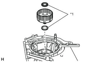
REMOVE MULTIPLE DISC CLUTCH HUB
-
*1 Thrust Bearing Race Remove the multiple disc clutch hub from the automatic transmission case sub-assembly.
-
Remove the 2 thrust bearing races from the multiple disc clutch hub.
-
- Click here
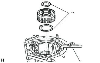
REMOVE FORWARD CLUTCH HUB SUB-ASSEMBLY
-
*1 Thrust Needle Roller Bearing Remove the forward clutch hub sub-assembly from the automatic transmission case sub-assembly.
-
Remove the 2 thrust needle roller bearings from the forward clutch hub sub-assembly.
-
- Click here
INSPECT FORWARD CLUTCH HUB SUB-ASSEMBLY
- Click here
REMOVE SUN GEAR INPUT DRUM SUB-ASSEMBLY
-
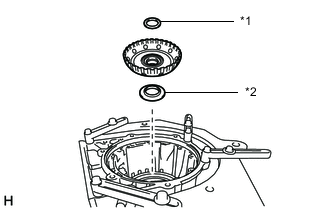
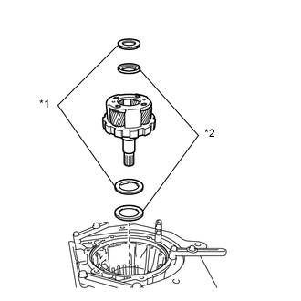
*1 Thrust Bearing Race *2 Thrust Needle Roller Bearing Remove the sun gear input drum sub-assembly from the automatic transmission case sub-assembly.
-
Remove the thrust needle roller bearing and thrust bearing race from the sun gear input drum sub-assembly.
-
- Click here
INSPECT SUN GEAR INPUT DRUM SUB-ASSEMBLY
- Click here
REMOVE FRONT PLANETARY GEAR ASSEMBLY
-
*1 Thrust Bearing Race Remove the front planetary gear assembly from the automatic transmission case sub-assembly.
-
Remove the 2 thrust bearing races from the front planetary gear assembly.
-
- Click here
INSPECT FRONT PLANETARY GEAR ASSEMBLY
- Click here
REMOVE FRONT PLANETARY RING GEAR WITH FRONT PLANETARY RING GEAR FLANGE SUB-ASSEMBLY
-
*1 Thrust Needle Roller Bearing *2 Thrust Bearing Race Remove the front planetary ring gear with front planetary ring gear flange sub-assembly from the automatic transmission case sub-assembly.
-
Remove the thrust needle roller bearing and thrust bearing race from the front planetary ring gear with front planetary ring gear flange sub-assembly.
-
- Click here
REMOVE FRONT PLANETARY RING GEAR FLANGE SUB-ASSEMBLY
-
*1 Front Planetary Ring Gear *2 Snap Ring *3 Front Planetary Ring Gear Flange Sub-assembly Using needle-nose pliers, remove the snap ring and front planetary ring gear flange sub-assembly from the front planetary ring gear.
-
- Click here
INSPECT FRONT PLANETARY RING GEAR FLANGE SUB-ASSEMBLY
- Click here
INSPECT CLEARANCE OF NO. 2 BRAKE
- Click here
REMOVE NO. 2 BRAKE CYLINDER WITH NO. 2 BRAKE PISTON
-
*a Turn Place SST on the No. 2 brake cylinder, and compress the No. 2 brake piston return spring sub-assembly with a press.
09380-60011 09381-06010 09381-06020 09381-06040 09381-06050 09381-06060 09381-06090 09381-06100 09381-06110 09381-06120 -
Using a screwdriver, remove the snap ring from the automatic transmission case sub-assembly.
Note:Be careful not to damage the automatic transmission case sub-assembly.
Tip:Tape the screwdriver tip before use.
-
*1 No. 2 Brake Cylinder with No. 2 Brake Piston *2 No. 2 Brake Piston Return Spring Sub-assembly Remove the No. 2 brake cylinder with No. 2 brake piston and No. 2 brake piston return spring sub-assembly from the automatic transmission case sub-assembly.
-
- Click here
INSPECT NO. 2 BRAKE PISTON RETURN SPRING SUB-ASSEMBLY
- Click here
REMOVE NO. 2 BRAKE PISTON
-
While holding the No. 2 brake piston, apply compressed air to the oil hole of the No. 2 brake cylinder to remove the No. 2 brake piston from the No. 2 brake cylinder.
-
Remove the 2 O-rings from the No. 2 brake piston.
-
- Click here
REMOVE NO. 2 BRAKE DISC
-
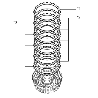
*1 No. 2 Brake Flange *2 No. 2 Brake Disc *3 No. 2 Brake Plate Remove the 2 No. 2 brake flanges, 5 No. 2 brake discs and 4 No. 2 brake plates from the automatic transmission case sub-assembly.
-
- Click here
INSPECT NO. 2 BRAKE DISC
- Click here
REMOVE CENTER PLANETARY RING GEAR FLANGE WITH CENTER PLANETARY RING GEAR
-
*1 Thrust Needle Roller Bearing Remove the center planetary ring gear flange with center planetary ring gear from the automatic transmission case sub-assembly.
-
Remove the 2 thrust needle roller bearings from the center planetary ring gear flange with center planetary ring gear.
-
- Click here
REMOVE CENTER PLANETARY RING GEAR
-
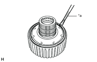
*a Protective Tape Using a screwdriver, remove the snap ring from the center planetary ring gear flange with center planetary ring gear.
Note:Be careful not to damage the center planetary ring gear flange with center planetary ring gear.
Tip:Tape the screwdriver tip before use.
-
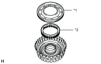
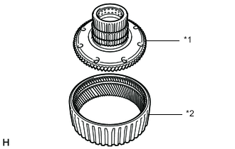
*1 Center Planetary Ring Gear Flange *2 Center Planetary Ring Gear Remove the center planetary ring gear from the center planetary ring gear flange.
-
- Click here
REMOVE CENTER PLANETARY GEAR ASSEMBLY
-
*1 Thrust Bearing Race Remove the center planetary gear assembly from the automatic transmission case sub-assembly.
-
Remove the thrust bearing race from the center planetary gear assembly.
-
- Click here
INSPECT CENTER PLANETARY GEAR ASSEMBLY
- Click here
REMOVE PLANETARY SUN GEAR
-
Remove the planetary sun gear from the automatic transmission case sub-assembly.
-
- Click here
INSPECT CLEARANCE OF NO. 1 BRAKE
- Click here
REMOVE NO. 1 BRAKE DISC
-
*a Protective Tape Using a screwdriver, remove the snap ring from the automatic transmission case sub-assembly.
Note:Be careful not to damage the automatic transmission case sub-assembly.
Tip:Tape the screwdriver tip before use.
-
*1 No. 1 Brake Flange *2 No. 1 Brake Disc *3 No. 1 Brake Plate Remove the No. 1 brake flange, 4 No. 1 brake discs and 4 No. 1 brake plates from the automatic transmission case sub-assembly.
-
- Click here
INSPECT NO. 1 BRAKE DISC
- Click here
REMOVE NO. 1 BRAKE CYLINDER WITH NO. 1 BRAKE PISTON
-
*a Turn Place SST on the No. 1 brake piston return spring sub-assembly, and compress the No. 1 brake piston return spring sub-assembly with a press.
09380-60011 09381-06010 09381-06040 09381-06050 09381-06070 09381-06090 09381-06100 09381-06110 09381-06120 -
Using a screwdriver, remove the snap ring from the automatic transmission case sub-assembly.
Note:Be careful not to damage the automatic transmission case sub-assembly.
Tip:Tape the screwdriver tip before use.
-
*1 No. 1 Brake Piston Return Spring Sub-assembly *2 No. 1 Brake Cylinder with No. 1 Brake Piston Remove the No. 1 brake piston return spring sub-assembly and No. 1 brake cylinder with No. 1 brake piston from the automatic transmission case sub-assembly.
-
- Click here
INSPECT NO. 1 BRAKE PISTON RETURN SPRING SUB-ASSEMBLY
- Click here
REMOVE NO. 1 BRAKE PISTON
-
While holding the No. 1 brake piston, apply compressed air to the oil hole of the No. 1 brake cylinder to remove the No. 1 brake piston from the No. 1 brake cylinder.
-
Remove the 2 O-rings from the No. 1 brake piston.
-
- Click here
INSPECT CLEARANCE OF NO. 4 BRAKE
- Click here
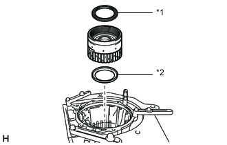
REMOVE INTERMEDIATE SHAFT WITH NO. 3 ONE-WAY CLUTCH ASSEMBLY AND REAR PLANETARY RING GEAR
-
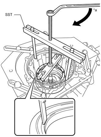
Using SST, remove the snap ring from the automatic transmission case sub-assembly.
09350-30020 09350-07060 -
Remove the intermediate shaft with No. 3 one-way clutch assembly and rear planetary ring gear from the automatic transmission case sub-assembly.
-
- Click here
INSPECT NO. 3 ONE-WAY CLUTCH ASSEMBLY
- Click here
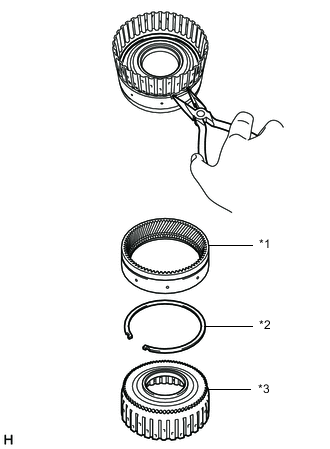
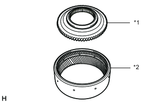
REMOVE NO. 3 ONE-WAY CLUTCH ASSEMBLY WITH ONE-WAY CLUTCH INNER RACE
-
*1 No. 3 One-way Clutch Assembly with One-way Clutch Inner Race *2 Intermediate Shaft with Rear Planetary Ring Gear Remove the No. 3 one-way clutch assembly with one-way clutch inner race from the intermediate shaft with rear planetary ring gear.
-
- Click here
REMOVE ONE-WAY CLUTCH INNER RACE
-
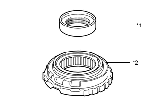
*1 One-way Clutch Inner Race *2 No. 3 One-way Clutch Assembly Remove the one-way clutch inner race from the No. 3 one-way clutch assembly.
-
- Click here
REMOVE REAR PLANETARY RING GEAR FLANGE SUB-ASSEMBLY WITH REAR PLANETARY RING GEAR
-
*1 Rear Planetary Ring Gear Flange Sub-assembly with Rear Planetary Ring Gear *2 Thrust Bearing Race Remove the rear planetary ring gear flange sub-assembly with rear planetary ring gear from the intermediate shaft.
-
Remove the thrust bearing race from the rear planetary ring gear flange sub-assembly with rear planetary ring gear.
-
*1 Thrust Needle Roller Bearing *2 Thrust Bearing Race Remove the thrust needle roller bearing and thrust bearing race from the intermediate shaft.
-
- Click here
INSPECT REAR PLANETARY RING GEAR FLANGE SUB-ASSEMBLY
- Click here
INSPECT INTERMEDIATE SHAFT
- Click here
REMOVE REAR PLANETARY RING GEAR
-
*a Protective Tape Using a screwdriver, remove the snap ring from the rear planetary ring gear flange sub-assembly with rear planetary ring gear.
Note:Be careful not to damage the rear planetary ring gear flange sub-assembly with rear planetary ring gear.
Tip:Tape the screwdriver tip before use.
-
*1 Rear Planetary Ring Gear Flange Sub-assembly *2 Rear Planetary Ring Gear Remove the rear planetary ring gear from the rear planetary ring gear flange sub-assembly.
-
- Click here
REMOVE REAR PLANETARY GEAR ASSEMBLY WITH NO. 4 BRAKE DISC
-
*1 Thrust Needle Roller Bearing *2 Thrust Bearing Race Remove the rear planetary gear assembly with No.4 brake disc from the automatic transmission case sub-assembly.
-
Remove the 2 thrust needle roller bearings and thrust bearing race from the rear planetary gear assembly with No. 4 brake disc.
-
Remove the thrust bearing race from the automatic transmission case sub-assembly.
-
- Click here
INSPECT REAR PLANETARY GEAR ASSEMBLY
- Click here
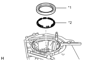
REMOVE NO. 4 BRAKE DISC
-
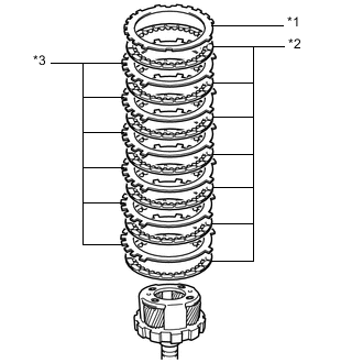
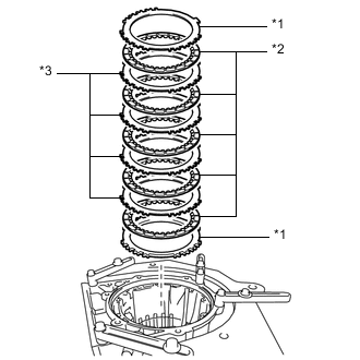
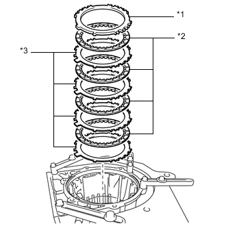
*1 No. 4 Brake Flange *2 No. 4 Brake Disc *3 No. 4 Brake Plate Remove the No. 4 brake flange, 7 No. 4 brake discs and 6 No. 4 brake plates from the rear planetary gear assembly.
-
Remove the No. 4 brake flange from the automatic transmission case sub-assembly.
-
- Click here
INSPECT NO. 4 BRAKE DISC
- Click here
REMOVE 1ST AND REVERSE BRAKE PISTON
-
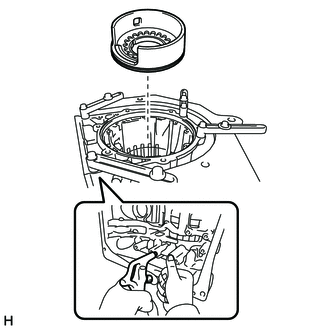
Place SST on the 1st and reverse brake return spring sub-assembly and compress the 1st and reverse brake return spring sub-assembly.
09380-60011 09381-05040 09381-05050 09381-06030 09381-06040 09381-06080 09381-06120 09381-06130 09381-06140 -
Using SST, remove the snap ring from the automatic transmission case sub-assembly.
09350-30020 09350-07070 -
Remove the 1st and reverse brake return spring sub-assembly from the automatic transmission case sub-assembly.
-
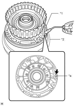
Apply compressed air to the oil hole of the automatic transmission case sub-assembly to remove the 1st and reverse brake piston from the automatic transmission case sub-assembly.
-
Remove the O-ring from the 1st and reverse brake piston.
-
- Click here
INSPECT 1ST AND REVERSE BRAKE RETURN SPRING SUB-ASSEMBLY
- Click here
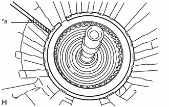
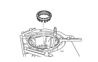
REMOVE BRAKE REACTION SLEEVE
-
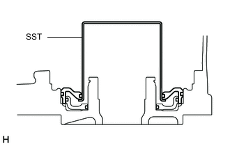
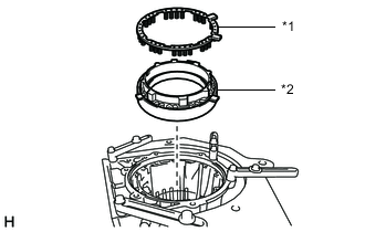
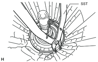
Using SST, remove the brake reaction sleeve from the automatic transmission case sub-assembly.
09350-30020 09350-07080 -
Remove the 2 O-rings from the brake reaction sleeve.
-
- Click here
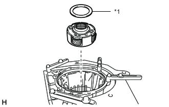
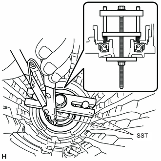
REMOVE NO. 4 BRAKE PISTON
-
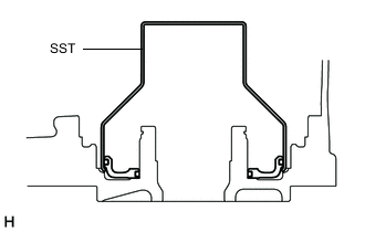
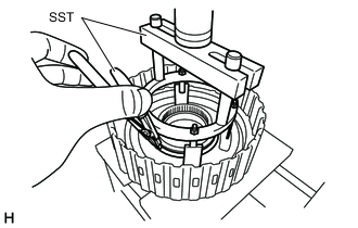
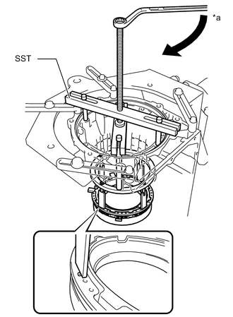
Using SST, remove the No. 4 brake piston from the automatic transmission case sub-assembly.
09350-30020 09350-07090 -
Remove the 2 O-rings from the No. 4 brake piston.
-
- Click here
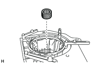
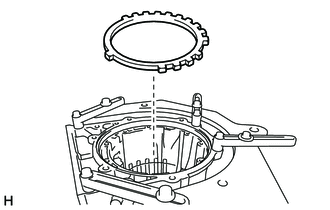
REMOVE BRAKE PLATE STOPPER SPRING
-
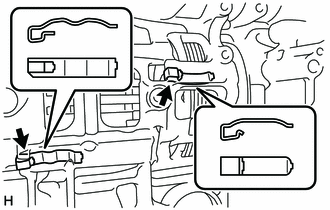
Remove the 2 brake plate stopper springs from the automatic transmission case sub-assembly.
-