RADIO RECEIVER INSTALLATION
CAUTION / NOTICE / HINT
Tech Tips
-
Use the same procedure for RHD and LHD vehicles.
-
The procedure listed below is for LHD vehicles.
PROCEDURE
-
INSTALL RADIO AND DISPLAY RECEIVER ASSEMBLY (for Radio and Display Type)
-
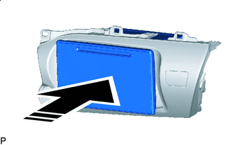

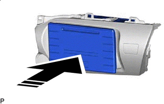
Install in this Direction Insert the radio and display receiver assembly in the direction of the arrow shown in the illustration to install it.
-
-
INSTALL NO. 2 RADIO BRACKET (for Radio and Display Type)
-
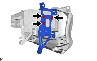
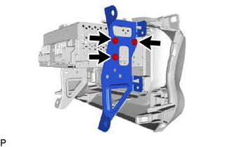
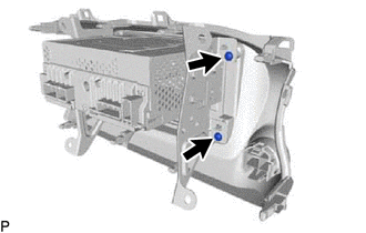
Install the No. 2 radio bracket to the radio and display receiver assembly with the 3 screws.
-
Install the 2 screws.
-
-
INSTALL NO. 1 RADIO BRACKET (for Radio and Display Type)
-
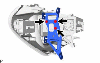
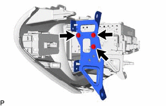
Install the No. 1 radio bracket to the radio and display receiver assembly with the 3 screws.
-
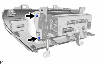
Install the 2 screws.
-
-
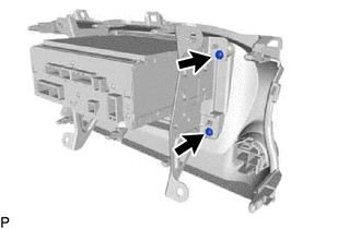
INSTALL RADIO AND DISPLAY RECEIVER ASSEMBLY WITH BRACKET (for Radio and Display Type)
-
Connect all the connectors.
-
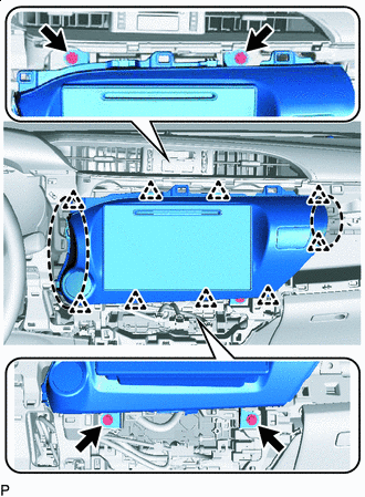

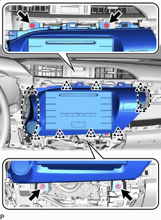
Place Hands Here Insert the radio and display receiver assembly with bracket to attach the clips on its backside.
Note
When inserting the radio and display receiver assembly, do not press the knobs on it.
-
Install the radio and display receiver assembly with bracket with the 4 screws.
-
-
INSTALL RADIO RECEIVER ASSEMBLY (for Radio Receiver Type)
-
Install in this Direction Insert the radio receiver assembly in the direction of the arrow shown in the illustration to install it.
-
-
INSTALL NO. 2 RADIO BRACKET (for Radio Receiver Type)
-
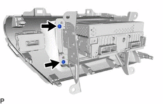
Install the No. 2 radio bracket to the radio receiver assembly with the 3 screws.
-
Install the 2 screws.
-
-
INSTALL NO. 1 RADIO BRACKET (for Radio Receiver Type)
-
Install the No. 1 radio bracket to the radio receiver assembly with the 3 screws.
-
Install the 2 screws.
-
-
INSTALL RADIO RECEIVER ASSEMBLY WITH BRACKET (for Radio Receiver Type)
-
Connect all the connectors.
-
Place Hands Here Insert the radio receiver assembly with bracket to attach the clips on its backside.
Note
When inserting the radio receiver assembly, do not press the knobs on it.
-
Install the radio receiver assembly with bracket with the 4 screws.
-
-
INSTALL AIR CONDITIONING CONTROL ASSEMBLY (for Automatic Air Conditioning System)
-
CONNECT AIR MIX DAMPER CONTROL CABLE SUB-ASSEMBLY (for Manual Air Conditioning System)
-
CONNECT AIR INLET DAMPER CONTROL CABLE SUB-ASSEMBLY (for Manual Air Conditioning System)
-
CONNECT DEFROSTER DAMPER CONTROL CABLE SUB-ASSEMBLY (for Manual Air Conditioning System)
-
INSTALL INTEGRATION PANEL SUB-ASSEMBLY WITH AIR CONDITIONING CONTROL ASSEMBLY (for Manual Air Conditioning System)
-
INSTALL AIR INLET DAMPER CONTROL LEVER (for Manual Air Conditioning System)
-
INSTALL CONTROL KNOB SUB-ASSEMBLY (for Manual Air Conditioning System)
-
CONNECT AIR INLET DAMPER CONTROL CABLE SUB-ASSEMBLY (for Manual Cooler System)
-
CONNECT DEFROSTER DAMPER CONTROL CABLE SUB-ASSEMBLY (for Manual Cooler System)
-
INSTALL INTEGRATION PANEL SUB-ASSEMBLY WITH AIR CONDITIONING CONTROL ASSEMBLY (for Manual Cooler System)
-
INSTALL AIR INLET DAMPER CONTROL LEVER (for Manual Cooler System)
-
INSTALL CONTROL KNOB SUB-ASSEMBLY (for Manual Cooler System)
-
INSTALL INSTRUMENT CLUSTER FINISH PANEL ASSEMBLY
-
INSTALL NO. 1 INSTRUMENT PANEL BOX DOOR SUB-ASSEMBLY
-
INSTALL INSTRUMENT CLUSTER FINISH PANEL GARNISH ASSEMBLY
-
INSTALL STEERING WHEEL ASSEMBLY
-
CONNECT CABLE TO NEGATIVE BATTERY TERMINAL
Note
When disconnecting the cable, some systems need to be initialized after the cable is reconnected Click here.