AUDIO AND VISUAL SYSTEM(for Radio and Display Type), Diagnostic DTC:B15C3
| DTC Code | DTC Name |
|---|---|
| B15C3 | Speaker Output Short |
DESCRIPTION
This DTC is stored when a malfunction occurs in the speakers.
| DTC No. | Detection Item | DTC Detection Condition | Trouble Area |
|---|---|---|---|
| B15C3 | Speaker Output Short | A short is detected in the speaker output circuit |
|
-
*: w/ Telematics Transceiver
WIRING DIAGRAM
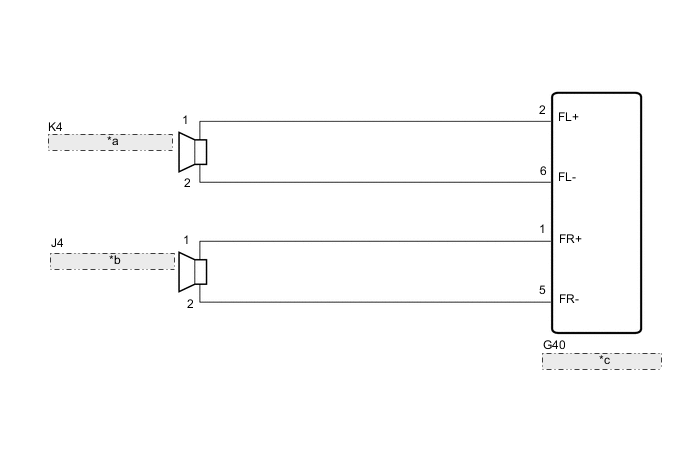
| *a | Front No. 1 Speaker Assembly LH |
| *b | Front No. 1 Speaker Assembly RH |
| *c | Radio and Display Receiver Assembly |
CAUTION / NOTICE / HINT
Note
Depending on the parts that are replaced during vehicle inspection or maintenance, performing initialization, registration or calibration may be needed. Refer to Precaution for Audio and Visual System.
PROCEDURE
-
CHECK DTC
-
Clear the DTCs.
Body Electrical > Navigation System > Clear DTCs -
Recheck for DTCs and check that no DTCs are output.
Body Electrical > Navigation System > Trouble CodesOK No DTCs are output. Result Result Proceed to OK A NG (for 2 Speakers, for 4 Speakers [Single Cab]) B NG (for 4 Speakers [Double Cab, Smart Cab]) C NG (for 6 Speakers) D
A 
USE SIMULATION METHOD TO CHECK Click here
C 
CHECK HARNESS AND CONNECTOR (SPEAKER CIRCUIT) Click here
D
CHECK HARNESS AND CONNECTOR (SPEAKER CIRCUIT) Click here
B 
-
-
CHECK HARNESS AND CONNECTOR (SPEAKER CIRCUIT)
-
*1: for LH Side
-
*2: for RH Side
-
Disconnect the G40 radio and display receiver assembly connector.
-
Disconnect the K4*1 and/or J4*2 front No. 1 speaker assembly connector.
-
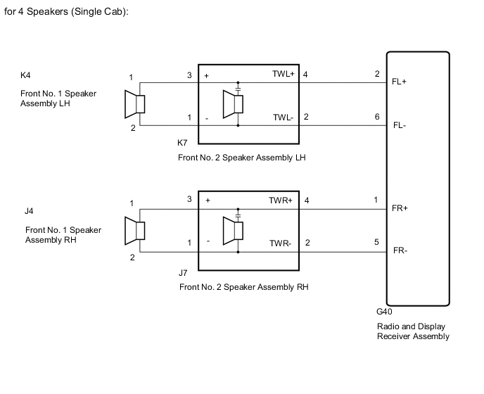
for 4 Speakers (Single Cab):
Disconnect the K7*1 and/or J7*2 front No. 2 speaker assembly connector.
-
Measure the resistance according to the value(s) in the table below.
Standard Resistance for LH Side (for 2 Speakers): Tester Connection Condition Specified Condition G40-2 (FL+) - K4-1 Always Below 1 Ω G40-6 (FL-) - K4-2 Always Below 1 Ω G40-2 (FL+) or K4-1 - Body ground Always 10 kΩ or higher G40-6 (FL-) or K4-2 - Body ground Always 10 kΩ or higher for LH Side (for 4 Speakers [Single Cab]): Tester Connection Condition Specified Condition G40-2 (FL+) - K7-4 (TWL+) Always Below 1 Ω G40-6 (FL-) - K7-2 (TWL-) Always Below 1 Ω K7-3 (+) - K4-1 Always Below 1 Ω K7-1 (-) - K4-2 Always Below 1 Ω G40-2 (FL+) or K7-4 (TWL+) - Body ground Always 10 kΩ or higher G40-6 (FL-) or K7-2 (TWL-) - Body ground Always 10 kΩ or higher K7-3 (+) or K4-1 - Body ground Always 10 kΩ or higher K7-1 (-) or K4-2 - Body ground Always 10 kΩ or higher for RH Side (for 2 Speakers): Tester Connection Condition Specified Condition G40-1 (FR+) - J4-1 Always Below 1 Ω G40-5 (FR-) - J4-2 Always Below 1 Ω G40-1 (FR+) or J4-1 - Body ground Always 10 kΩ or higher G40-5 (FR-) or J4-2 - Body ground Always 10 kΩ or higher for RH Side (for 4 Speakers [Single Cab]): Tester Connection Condition Specified Condition G40-1 (FR+) - J7-4 (TWR+) Always Below 1 Ω G40-5 (FR-) - J7-2 (TWR-) Always Below 1 Ω J7-3 (+) - J4-1 Always Below 1 Ω J7-1 (-) - J4-2 Always Below 1 Ω G40-1 (FR+) or J7-4 (TWR+) - Body ground Always 10 kΩ or higher G40-5 (FR-) or J7-2 (TWR-) - Body ground Always 10 kΩ or higher J7-3 (+) or J4-1 - Body ground Always 10 kΩ or higher J7-1 (-) or J4-2 - Body ground Always 10 kΩ or higher Result Proceed to OK NG
NG
REPAIR OR REPLACE HARNESS OR CONNECTOR
OK
-
-
INSPECT FRONT NO. 1 SPEAKER ASSEMBLY
-
Remove the front No. 1 speaker assembly.
-
Inspect the front No. 1 speaker assembly.
Result Result Proceed to OK (for 2 Speakers) A OK (for 4 Speakers [Single Cab]) B NG C
A
REPLACE RADIO AND DISPLAY RECEIVER ASSEMBLY Click here
C
REPLACE FRONT NO. 1 SPEAKER ASSEMBLY Click here
B
-
-
CHECK FRONT NO. 2 SPEAKER ASSEMBLY
-
Replace the front No. 2 speaker assembly with a new or known good one.
-
Clear the DTCs.
Body Electrical > Navigation System > Clear DTCs -
Recheck for DTCs and check that no DTCs are output.
Body Electrical > Navigation System > Trouble CodesOK No DTCs are output. Result Proceed to OK NG
OK
END (FRONT NO. 2 SPEAKER ASSEMBLY IS DEFECTIVE)
NG
REPLACE RADIO AND DISPLAY RECEIVER ASSEMBLY Click here
-
-
CHECK HARNESS AND CONNECTOR (SPEAKER CIRCUIT)
-
*1: for LH Side
-
*2: for RH Side
-
*3: w/o Telematics Transceiver
-
*4: w/ Telematics Transceiver
-
Disconnect the G40 and G41 radio and display receiver assembly connectors.
-
Disconnect the K4*1 and/or J4*2 front No. 1 speaker assembly connector.
-
Disconnect the M2*1 and/or L2*2 rear speaker assembly connector.
-
Disconnect the G130 telematics transceiver connector.*4
-
Measure the resistance according to the value(s) in the table below.
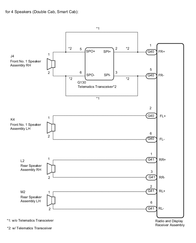
Standard Resistance for LH Side: Tester Connection Condition Specified Condition G40-2 (FL+) - K4-1 Always Below 1 Ω G40-6 (FL-) - K4-2 Always Below 1 Ω G41-2 (RL+) - M2-1 Always Below 1 Ω G41-6 (RL-) - M2-2 Always Below 1 Ω G40-2 (FL+) or K4-1 - Body ground Always 10 kΩ or higher G40-6 (FL-) or K4-2 - Body ground Always 10 kΩ or higher G41-2 (RL+) or M2-1 - Body ground Always 10 kΩ or higher G41-6 (RL-) or M2-2 - Body ground Always 10 kΩ or higher for RH Side: Tester Connection Condition Specified Condition G40-1 (FR+) - J4-1*3 Always Below 1 Ω G40-1 (FR+) - G130-2 (SPI+)*4 Always Below 1 Ω G40-5 (FR-) - J4-2*3 Always Below 1 Ω G40-5 (FR-) - G130-3 (SPI-)*4 Always Below 1 Ω G130-5 (SPO+) - J4-1*4 Always Below 1 Ω G130-6 (SPO-) - J4-2*4 Always Below 1 Ω G41-1 (RR+) - L2-1 Always Below 1 Ω G41-3 (RR-) - L2-2 Always Below 1 Ω G40-1 (FR+) or J4-1 - Body ground*3 Always 10 kΩ or higher G40-1 (FR+) or G130-2 (SPI+) - Body ground*4 Always 10 kΩ or higher G40-5 (FR-) or J4-2 - Body ground*3 Always 10 kΩ or higher G40-5 (FR-) or G130-3 (SPI-) - Body ground*4 Always 10 kΩ or higher G130-5 (SPO+) or J4-1 - Body ground*4 Always 10 kΩ or higher G130-6 (SPO-) or J4-2 - Body ground*4 Always 10 kΩ or higher G41-1 (RR+) or L2-1 - Body ground Always 10 kΩ or higher G41-3 (RR-) or L2-2 - Body ground Always 10 kΩ or higher Result Proceed to OK NG
NG
REPAIR OR REPLACE HARNESS OR CONNECTOR
OK
-
-
INSPECT FRONT NO. 1 SPEAKER ASSEMBLY
-
Remove the front No. 1 speaker assembly.
-
Inspect the front No. 1 speaker assembly.
Result Proceed to OK NG
NG
REPLACE FRONT NO. 1 SPEAKER ASSEMBLY Click here
OK
-
-
INSPECT REAR SPEAKER ASSEMBLY
-
Remove the rear speaker assembly.
for Smart Cab: Click here
for Double Cab: Click here
-
Inspect the rear speaker assembly.
for Smart Cab: Click here
for Double Cab: Click here
Result Result Proceed to OK (w/ Telematics Transceiver) A OK (w/o Telematics Transceiver) B NG C
A
GO TO STEP 12 Click here
B
REPLACE RADIO AND DISPLAY RECEIVER ASSEMBLY Click here
C
REPLACE REAR SPEAKER ASSEMBLY for Smart Cab: Click here
REPLACE REAR SPEAKER ASSEMBLY for Double Cab: Click here -
-
CHECK HARNESS AND CONNECTOR (SPEAKER CIRCUIT)
-
*1: for LH Side
-
*2: for RH Side
-
*3: w/o Telematics Transceiver
-
*4: w/ Telematics Transceiver
-
Disconnect the G40 and G41 radio and display receiver assembly connectors.
-
Disconnect the K4*1 and/or J4*2 front No. 1 speaker assembly connector.
-
Disconnect the K7*1 and/or J7*2 front No. 2 speaker assembly connector.
-
Disconnect the M2*1 and/or L2*2 rear speaker assembly connector.
-
Disconnect the G130 telematics transceiver connector.*4
-
Measure the resistance according to the value(s) in the table below.
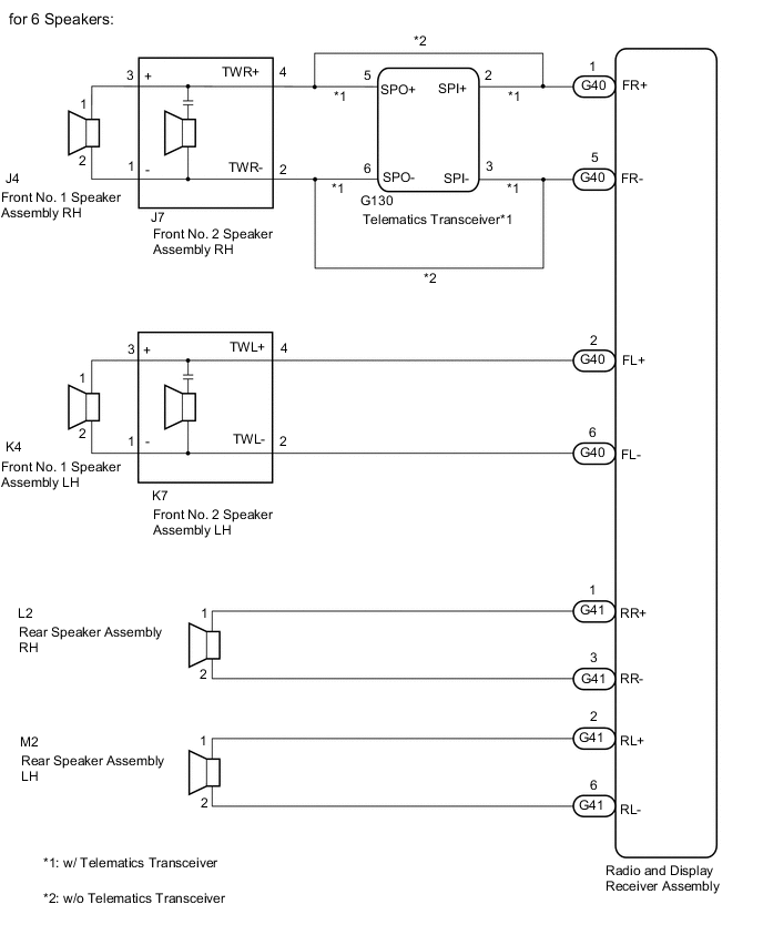
Standard Resistance for LH Side: Tester Connection Condition Specified Condition G40-2 (FL+) - K7-4 (TWL+) Always Below 1 Ω G40-6 (FL-) - K7-2 (TWL-) Always Below 1 Ω K7-3 (+) - K4-1 Always Below 1 Ω K7-1 (-) - K4-2 Always Below 1 Ω G41-2 (RL+) - M2-1 Always Below 1 Ω G41-6 (RL-) - M2-2 Always Below 1 Ω G40-2 (FL+) or K7-4 (TWL+) - Body ground Always 10 kΩ or higher G40-6 (FL-) or K7-2 (TWL-) - Body ground Always 10 kΩ or higher K7-3 (+) or K4-1 - Body ground Always 10 kΩ or higher K7-1 (-) or K4-2 - Body ground Always 10 kΩ or higher G41-2 (RL+) or M2-1 - Body ground Always 10 kΩ or higher G41-6 (RL-) or M2-2 - Body ground Always 10 kΩ or higher for RH Side: Tester Connection Condition Specified Condition G40-1 (FR+) - J7-4 (TWR+)*3 Always Below 1 Ω G40-1 (FR+) - G130-2 (SPI+)*4 Always Below 1 Ω G40-5 (FR-) - J7-2 (TWR-)*3 Always Below 1 Ω G40-5 (FR-) - G130-3 (SPI-)*4 Always Below 1 Ω G130-5 (SPO+) - J7-4 (TWR+)*4 Always Below 1 Ω G130-6 (SPO-) - J7-2 (TWR-)*4 Always Below 1 Ω J7-3 (+) - J4-1 Always Below 1 Ω J7-1 (-) - J4-2 Always Below 1 Ω G41-1 (RR+) - L2-1 Always Below 1 Ω G41-3 (RR-) - L2-2 Always Below 1 Ω G40-1 (FR+) or J7-4 (TWR+) - Body ground*3 Always 10 kΩ or higher G40-1 (FR+) or G130-2 (SPI+) - Body ground*4 Always 10 kΩ or higher G40-5 (FR-) or J7-2 (TWR-) - Body ground*3 Always 10 kΩ or higher G40-5 (FR-) or G130-3 (SPI-) - Body ground*4 Always 10 kΩ or higher G130-5 (SPO+) or J7-4 (TWR+) - Body ground*4 Always 10 kΩ or higher G130-6 (SPO-) or J7-2 (TWR-) - Body ground*4 Always 10 kΩ or higher J7-3 (+) or J4-1 - Body ground Always 10 kΩ or higher J7-1 (-) or J4-2 - Body ground Always 10 kΩ or higher G41-1 (RR+) or L2-1 - Body ground Always 10 kΩ or higher G41-3 (RR-) or L2-2 - Body ground Always 10 kΩ or higher Result Proceed to OK NG
NG
REPAIR OR REPLACE HARNESS OR CONNECTOR
OK
-
-
INSPECT FRONT NO. 1 SPEAKER ASSEMBLY
-
Remove the front No. 1 speaker assembly.
-
Inspect the front No. 1 speaker assembly.
Result Proceed to OK NG
NG
REPLACE FRONT NO. 1 SPEAKER ASSEMBLY Click here
OK
-
-
INSPECT REAR SPEAKER ASSEMBLY
-
Remove the rear speaker assembly.
for Smart Cab:
for Double Cab:
-
Inspect the rear speaker assembly.
for Smart Cab:
for Double Cab:
Result Proceed to OK NG
NG
REPLACE REAR SPEAKER ASSEMBLY for Smart Cab: REPLACE REAR SPEAKER ASSEMBLY Click here
REPLACE REAR SPEAKER ASSEMBLY for Double Cab: REPLACE REAR SPEAKER ASSEMBLY Click hereOK
-
-
CHECK FRONT NO. 2 SPEAKER ASSEMBLY
-
Replace the front No. 2 speaker assembly with a new or known good one.
-
Clear the DTCs.
Body Electrical > Navigation System > Clear DTCs -
Recheck for DTCs and check that no DTCs are output.
Body Electrical > Navigation System > Trouble CodesOK No DTCs are output. Result Result Proceed to OK A NG (w/ Telematics Transceiver) B NG (w/o Telematics Transceiver) C
A
END (FRONT NO. 2 SPEAKER ASSEMBLY IS DEFECTIVE)
C
REPLACE RADIO AND DISPLAY RECEIVER ASSEMBLY Click here
B
-
-
CHECK TELEMATICS TRANSCEIVER
-
Replace the telematics transceiver with a new one.
-
Clear the DTCs.
Body Electrical > Navigation System > Clear DTCs -
Recheck for DTCs and check that no DTCs are output.
Body Electrical > Navigation System > Trouble CodesOK No DTCs are output. Result Proceed to OK NG
OK
END (TELEMATICS TRANSCEIVER IS DEFECTIVE)
NG
REPLACE RADIO AND DISPLAY RECEIVER ASSEMBLY Click here
-