AUDIO AND VISUAL SYSTEM(for Radio and Display Type) Reverse Signal Circuit
DESCRIPTION
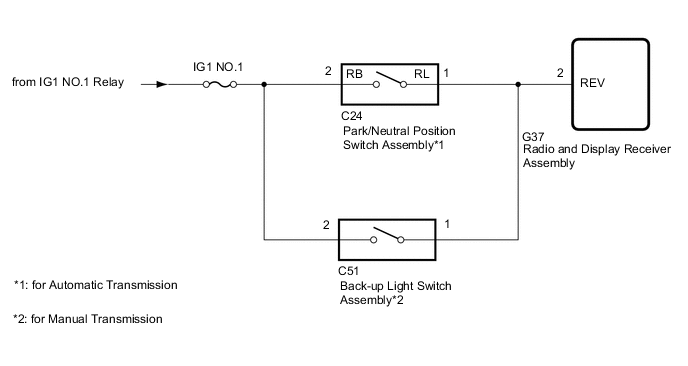
The radio and display receiver assembly a reverse signal from the park/neutral position switch assembly*1 or back-up light switch assembly*2 to use for adjusting the vehicle position on the display.
-
*1: for Automatic Transmission
-
*2: for Manual Transmission
WIRING DIAGRAM
CAUTION / NOTICE / HINT
Note
Inspect the fuses for circuits related to this system before performing the following procedure.
Tech Tips
When replacing the radio and display receiver assembly, it is necessary to perform the vehicle contract setting for Connected Services (w/ Connected Services Function).
PROCEDURE
-
CHECK VEHICLE SIGNAL (OPERATION CHECK)
-
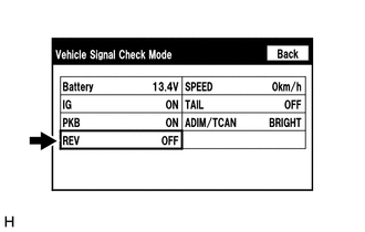
Enter the "Vehicle Signal Check Mode" screen.
Refer to check Vehicle Signal in Operation Check.
-
Check that the display changes between ON and OFF according to the shift lever position.
OK Shift Lever Position Display R ON Except R OFF Tech Tips
This display is updated once per second. As a result, it is normal for the display to lag behind the actual shift lever position.
Result Proceed to OK NG
OK 
PROCEED TO NEXT SUSPECTED AREA SHOWN IN PROBLEM SYMPTOMS TABLE Click here
NG 
-
-
CHECK RADIO AND DISPLAY RECEIVER ASSEMBLY (REVERSE SIGNAL)
-
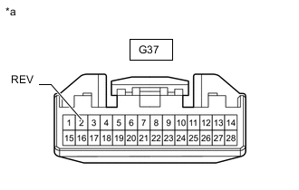
*a Front view of wire harness connector
(to Radio and Display Receiver Assembly)
Disconnect the radio and display receiver assembly connector.
-
Measure the voltage according to the value(s) in the table below.
Standard Voltage Tester Connection Switch Condition Specified Condition G37-2 (REV) - Body ground Ignition switch ON, shift lever in R 11 to 14 V G37-2 (REV) - Body ground Ignition switch ON, shift lever any position other than in R Below 1 V Result Result Proceed to OK A NG (for Automatic Transmission) B NG (for Manual Transmission) C
A
REPLACE RADIO AND DISPLAY RECEIVER ASSEMBLY Click here
C 
CHECK HARNESS AND CONNECTOR (RADIO AND DISPLAY RECEIVER ASSEMBLY - BACK-UP LIGHT SWITCH ASSEMBLY) Click here
B
-
-
CHECK HARNESS AND CONNECTOR (RADIO AND DISPLAY RECEIVER ASSEMBLY - PARK/NEUTRAL POSITION SWITCH ASSEMBLY)
-
Disconnect the G37 radio and display receiver assembly connector.
-
Disconnect the C24 park/neutral position switch assembly connector.
-
Measure the resistance according to the value(s) in the table below.
Standard Resistance Tester Connection Condition Specified Condition G37-2 (REV) - C24-1 (RL) Always Below 1 Ω G37-2 (REV) or C24-1 (RL) - Body ground Always 10 kΩ or higher Result Proceed to OK NG
NG
REPAIR OR REPLACE HARNESS OR CONNECTOR
OK
-
-
CHECK HARNESS AND CONNECTOR (PARK/NEUTRAL POSITION SWITCH ASSEMBLY - BATTERY)
-
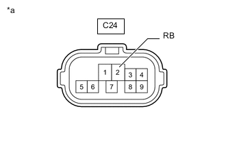
*a Front view of wire harness connector
(to Park/Neutral Position Switch Assembly)
Disconnect the park/neutral position switch assembly connector.
-
Measure the voltage according to the value(s) in the table below.
Standard Voltage Tester Connection Switch Condition Specified Condition C24-2 (RB) - Body ground Ignition switch ON 11 to 14 V Result Proceed to OK NG
OK
REPLACE PARK/NEUTRAL POSITION SWITCH ASSEMBLY A70F: Click here
REPLACE PARK/NEUTRAL POSITION SWITCH ASSEMBLY A60E: Click here
REPLACE PARK/NEUTRAL POSITION SWITCH ASSEMBLY A60F: Click hereNG
REPAIR OR REPLACE HARNESS OR CONNECTOR
-
-
CHECK HARNESS AND CONNECTOR (RADIO AND DISPLAY RECEIVER ASSEMBLY - BACK-UP LIGHT SWITCH ASSEMBLY)
-
Disconnect the G37 radio and display receiver assembly connector.
-
Disconnect the C51 back-up light switch assembly connector.
-
Measure the resistance according to the value(s) in the table below.
Standard Resistance Tester Connection Condition Specified Condition G37-2 (REV) - C51-1 Always Below 1 Ω G37-2 (REV) or C51-1 - Body ground Always 10 kΩ or higher Result Proceed to OK NG
NG
REPAIR OR REPLACE HARNESS OR CONNECTOR
OK
-
-
CHECK HARNESS AND CONNECTOR (BACK-UP LIGHT SWITCH ASSEMBLY - BATTERY)
-
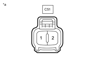
*a Front view of wire harness connector
(to Back-up Light Switch Assembly)
Disconnect the back-up light switch assembly connector.
-
Measure the voltage according to the value(s) in the table below.
Standard Voltage Tester Connection Switch Condition Specified Condition C51-2 - Body ground Ignition switch ON 11 to 14 V Result Proceed to OK NG
OK
REPLACE BACK-UP LIGHT SWITCH ASSEMBLY R151: Click here
REPLACE BACK-UP LIGHT SWITCH ASSEMBLY R151F: Click here
REPLACE BACK-UP LIGHT SWITCH ASSEMBLY RC60 / RC61: Click here
REPLACE BACK-UP LIGHT SWITCH ASSEMBLY RC60F / RC61F: Click hereNG
REPAIR OR REPLACE HARNESS OR CONNECTOR
-