AUDIO AND VISUAL SYSTEM(for Radio and Display Type) Speaker Circuit
DESCRIPTION
If there is a short in a speaker circuit, the radio and display receiver assembly detects it and stops output to the speakers.
As a result, sound cannot be heard from the speakers even if there is no malfunction in the radio and display receiver assembly or speakers.
WIRING DIAGRAM
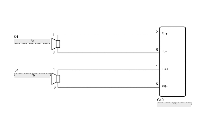
| *a | Front No. 1 Speaker Assembly LH |
| *b | Front No. 1 Speaker Assembly RH |
| *c | Radio and Display Receiver Assembly |
PROCEDURE
-
CHECK SPEAKER TYPE
-
Check speaker type.
Result Result Proceed to for 2 Speakers A for 4 Speakers B for 6 Speakers C
B 
CHECK HARNESS AND CONNECTOR (SPEAKER CIRCUIT) Click here
C
CHECK HARNESS AND CONNECTOR (SPEAKER CIRCUIT) Click here
A 
-
-
CHECK HARNESS AND CONNECTOR (SPEAKER CIRCUIT)
-
*1: for LH Side
*2: for RH Side
-
Disconnect the G40 radio and display receiver assembly connector.
-
Disconnect the K4*1 and/or J4*2 front No. 1 speaker assembly connector.
-
Measure the resistance according to the value(s) in the table below.
Standard Resistance for LH Side Tester Connection Condition Specified Condition G40-2 (FL+) - K4-1 Always Below 1 Ω G40-6 (FL-) - K4-2 Always Below 1 Ω G40-2 (FL+) or K4-1 - Body ground Always 10 kΩ or higher G40-6 (FL-) or K4-2 - Body ground Always 10 kΩ or higher for RH Side Tester Connection Condition Specified Condition G40-1 (FR+) - J4-1 Always Below 1 Ω G40-5 (FR-) - J4-2 Always Below 1 Ω G40-1 (FR+) or J4-1 - Body ground Always 10 kΩ or higher G40-5 (FR-) or J4-2 - Body ground Always 10 kΩ or higher Result Proceed to OK NG
NG 
REPAIR OR REPLACE HARNESS OR CONNECTOR
OK
-
-
INSPECT FRONT NO. 1 SPEAKER ASSEMBLY
-
Remove the front No. 1 speaker assembly.
-
Inspect the front No. 1 speaker assembly.
Result Proceed to OK NG
OK
PROCEED TO NEXT SUSPECTED AREA SHOWN IN PROBLEM SYMPTOMS TABLE Click here
NG
REPLACE FRONT NO. 1 SPEAKER ASSEMBLY Click here
-
-
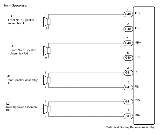
CHECK HARNESS AND CONNECTOR (SPEAKER CIRCUIT)
-
*1: for LH Side
*2: for RH Side
-
Disconnect the G40 and G41 radio and display receiver assembly connectors.
-
Disconnect the K4*1 and/or J4*2 front No. 1 speaker assembly connector.
-
Disconnect the M2*1 and/or L2*2 rear speaker assembly connector.
-
Measure the resistance according to the value(s) in the table below.
Standard Resistance for LH Side Tester Connection Condition Specified Condition G40-2 (FL+) - K4-1 Always Below 1 Ω G40-6 (FL-) - K4-2 Always Below 1 Ω G41-2 (RL+) - M2-1 Always Below 1 Ω G41-6 (RL-) - M2-2 Always Below 1 Ω G40-2 (FL+) or K4-1 - Body ground Always 10 kΩ or higher G40-6 (FL-) or K4-2 - Body ground Always 10 kΩ or higher G41-2 (RL+) or M2-1 - Body ground Always 10 kΩ or higher G41-6 (RL-) or M2-2 - Body ground Always 10 kΩ or higher for RH Side Tester Connection Condition Specified Condition G40-1 (FR+) - J4-1 Always Below 1 Ω G40-5 (FR-) - J4-2 Always Below 1 Ω G41-1 (RR+) - L2-1 Always Below 1 Ω G41-3 (RR-) - L2-2 Always Below 1 Ω G40-1 (FR+) or J4-1 - Body ground Always 10 kΩ or higher G40-5 (FR-) or J4-2 - Body ground Always 10 kΩ or higher G41-1 (RR+) or L2-1 - Body ground Always 10 kΩ or higher G41-3 (RR-) or L2-2 - Body ground Always 10 kΩ or higher Result Proceed to OK NG
NG
REPAIR OR REPLACE HARNESS OR CONNECTOR
OK
-
-
INSPECT FRONT NO. 1 SPEAKER ASSEMBLY
-
Remove the front No. 1 speaker assembly.
-
Inspect the front No. 1 speaker assembly.
Result Proceed to OK NG
NG
REPLACE FRONT NO. 1 SPEAKER ASSEMBLY Click here
OK
-
-
INSPECT REAR SPEAKER ASSEMBLY
-
Remove the rear speaker assembly.
for Smart Cab: Click here
for Double Cab: Click here
-
Inspect the rear speaker assembly.
for Smart Cab: Click here
for Double Cab: Click here
Result Proceed to OK NG
OK
PROCEED TO NEXT SUSPECTED AREA SHOWN IN PROBLEM SYMPTOMS TABLE Click here
NG
REPLACE REAR SPEAKER ASSEMBLY for Smart Cab: Click here
REPLACE REAR SPEAKER ASSEMBLY for Double Cab: Click here -
-
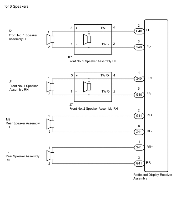
CHECK HARNESS AND CONNECTOR (SPEAKER CIRCUIT)
-
*1: for LH Side
*2: for RH Side
-
Disconnect the G40 and G41 radio and display receiver assembly connectors.
-
Disconnect the K4*1 and/or J4*2 front No. 1 speaker assembly connector.
-
Disconnect the K7*1 and/or J7*2 front No. 2 speaker assembly connector.
-
Disconnect the M2*1 and/or L2*2 rear speaker assembly connector.
-
Measure the resistance according to the value(s) in the table below.
Standard Resistance for LH Side Tester Connection Condition Specified Condition G40-2 (FL+) - K7-4 (TWL+) Always Below 1 Ω G40-6 (FL-) - K7-2 (TWL-) Always Below 1 Ω K7-3 (+) - K4-1 Always Below 1 Ω K7-1 (-) - K4-2 Always Below 1 Ω G41-2 (RL+) - M2-1 Always Below 1 Ω G41-6 (RL-) - M2-2 Always Below 1 Ω G40-2 (FL+) or K7-4 (TWL+) - Body ground Always 10 kΩ or higher G40-6 (FL-) or K7-2 (TWL-) - Body ground Always 10 kΩ or higher K7-3 (+) or K4-1 - Body ground Always 10 kΩ or higher K7-1 (-) or K4-2 - Body ground Always 10 kΩ or higher G41-2 (RL+) or M2-1 - Body ground Always 10 kΩ or higher G41-6 (RL-) or M2-2 - Body ground Always 10 kΩ or higher for RH Side Tester Connection Condition Specified Condition G40-1 (FR+) - J7-4 (TWR+) Always Below 1 Ω G40-5 (FR-) - J7-2 (TWR-) Always Below 1 Ω J7-3 (+) - J4-1 Always Below 1 Ω J7-1 (-) - J4-2 Always Below 1 Ω G41-1 (RR+) - L2-1 Always Below 1 Ω G41-3 (RR-) - L2-2 Always Below 1 Ω G40-1 (FR+) or J7-4 (TWR+) - Body ground Always 10 kΩ or higher G40-5 (FR-) or J7-2 (TWR-) - Body ground Always 10 kΩ or higher J7-3 (+) or J4-1 - Body ground Always 10 kΩ or higher J7-1 (-) or J4-2 - Body ground Always 10 kΩ or higher G41-1 (RR+) or L2-1 - Body ground Always 10 kΩ or higher G41-3 (RR-) or L2-2 - Body ground Always 10 kΩ or higher Result Proceed to OK NG
NG
REPAIR OR REPLACE HARNESS OR CONNECTOR
OK
-
-
INSPECT FRONT NO. 1 SPEAKER ASSEMBLY
-
Remove the front No. 1 speaker assembly.
-
Inspect the front No. 1 speaker assembly.
Result Proceed to OK NG
NG
REPLACE FRONT NO. 1 SPEAKER ASSEMBLY Click here
OK
-
-
INSPECT REAR SPEAKER ASSEMBLY
-
Remove the rear speaker assembly.
-
Inspect the rear speaker assembly.
Result Proceed to OK NG
NG
REPLACE REAR SPEAKER ASSEMBLY Click here
OK
-
-
CHECK FRONT NO. 2 SPEAKER ASSEMBLY
-
Replace the front No. 2 speaker assembly.
-
Check the malfunction disappears.
OK Malfunction disappears. Tech Tips
-
Connect all the connectors to the rear No. 2 speaker assemblies that were disconnected.
-
When there is a possibility that either the right or left front speaker is defective, inspect by interchanging the right one with the left one.
-
Perform the above inspection on both the LH and RH sides.
Result Proceed to OK NG -
OK
END (FRONT NO. 2 SPEAKER ASSEMBLY IS DEFECTIVE)
NG
PROCEED TO NEXT SUSPECTED AREA SHOWN IN PROBLEM SYMPTOMS TABLE Click here
-