| DTC Code | DTC Name |
|---|---|
| B15C3 | Speaker Output Short |
DESCRIPTION
This DTC is stored when a malfunction occurs in the speakers.
| DTC No. | Detection Item | DTC Detection Condition | Trouble Area |
|---|---|---|---|
| B15C3 | Speaker Output Short | A short is detected in the speaker output circuit |
|
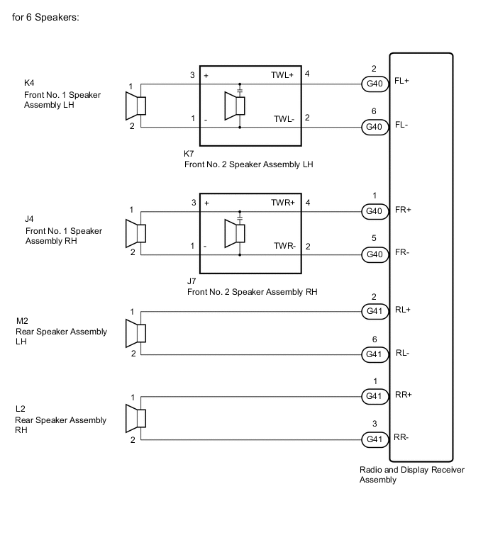
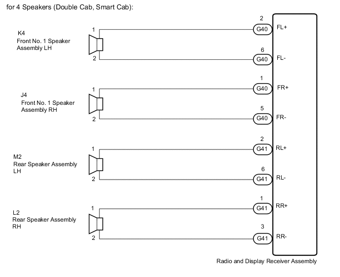
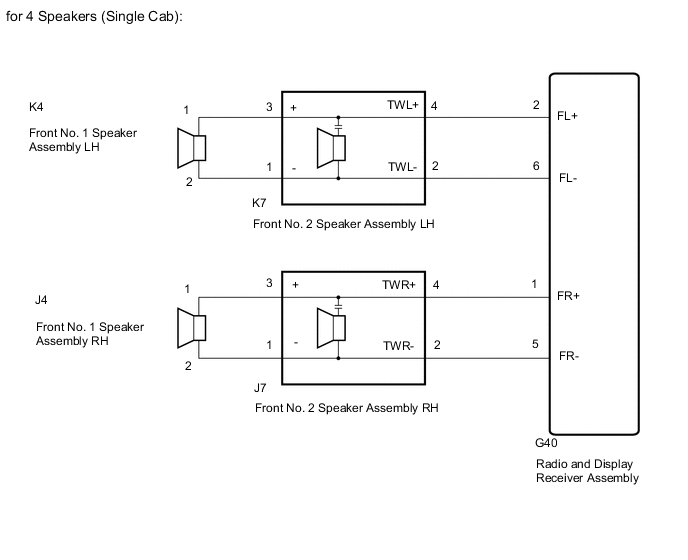
WIRING DIAGRAM
CAUTION / NOTICE / HINT
When replacing the radio and display receiver assembly, it is necessary to perform the vehicle contract setting for Connected Services (w/ Connected Services Function).
PROCEDURE
- Click here
CHECK DTC
-
Clear the DTCs.
- Body Electrical > Navigation System > Clear DTCs
-
-
-
Recheck for DTCs and check that no DTCs are output.
- Body Electrical > Navigation System > Trouble Codes
-
-
OK No DTCs are output. Result Result Proceed to OK A NG (for 2 Speakers, for 4 Speakers (Single Cab)) B NG (for 4 Speakers (Double Cab, Smart Cab)) C NG (for 6 Speakers) D
- A
USE SIMULATION METHOD TO CHECKClick here
- BClick here
- CClick here
- DClick here
-
- Click here
CHECK HARNESS AND CONNECTOR (SPEAKER CIRCUIT)
-
*1: for LH Side
-
*2: for RH Side
-
Disconnect the G40 radio and display receiver assembly connector.
-
Disconnect the K4*1 and/or J4*2 front No. 1 speaker assembly connector.
-
for 4 Speakers (Single Cab):
Disconnect the K7*1 and/or J7*2 front No. 2 speaker assembly connector.
-
Measure the resistance according to the value(s) in the table below.
Standard Resistance Table 2. for LH Side (for 2 Speakers) Tester Connection Condition Specified Condition G40-2 (FL+) - K4-1 Always Below 1 Ω G40-6 (FL-) - K4-2 Always Below 1 Ω G40-2 (FL+) or K4-1 - Body ground Always 10 kΩ or higher G40-6 (FL-) or K4-2 - Body ground Always 10 kΩ or higher Table 3. for LH Side (for 4 Speakers (Single Cab)) Tester Connection Condition Specified Condition G40-2 (FL+) - K7-4 (TWL+) Always Below 1 Ω G40-6 (FL-) - K7-2 (TWL-) Always Below 1 Ω K7-3 (+) - K4-1 Always Below 1 Ω K7-1 (-) - K4-2 Always Below 1 Ω G40-2 (FL+) or K7-4 (TWL+) - Body ground Always 10 kΩ or higher G40-6 (FL-) or K7-2 (TWL-) - Body ground Always 10 kΩ or higher K7-3 (+) or K4-1 - Body ground Always 10 kΩ or higher K7-1 (-) or K4-2 - Body ground Always 10 kΩ or higher Table 4. for RH Side (for 2 Speakers) Tester Connection Condition Specified Condition G40-1 (FR+) - J4-1 Always Below 1 Ω G40-5 (FR-) - J4-2 Always Below 1 Ω G40-1 (FR+) or J4-1 - Body ground Always 10 kΩ or higher G40-5 (FR-) or J4-2 - Body ground Always 10 kΩ or higher Table 5. for RH Side (for 4 Speakers (Single Cab)) Tester Connection Condition Specified Condition G40-1 (FR+) - J7-4 (TWR+) Always Below 1 Ω G40-5 (FR-) - J7-2 (TWR-) Always Below 1 Ω J7-3 (+) - J4-1 Always Below 1 Ω J7-1 (-) - J4-2 Always Below 1 Ω G40-1 (FR+) or J7-4 (TWR+) - Body ground Always 10 kΩ or higher G40-5 (FR-) or J7-2 (TWR-) - Body ground Always 10 kΩ or higher J7-3 (+) or J4-1 - Body ground Always 10 kΩ or higher J7-1 (-) or J4-2 - Body ground Always 10 kΩ or higher Result Proceed to OK NG
- OKClick here
- NG
REPAIR OR REPLACE HARNESS OR CONNECTOR
-
- Click here
INSPECT FRONT NO. 1 SPEAKER ASSEMBLY
-
Remove the front No. 1 speaker assembly.
-
Inspect the front No. 1 speaker assembly.
Result Proceed to OK (for 2 Speakers) OK (for 4 Speakers (Single Cab)) NG
- OK (for 2 Speakers)
REPLACE RADIO AND DISPLAY RECEIVER ASSEMBLYClick here
- OK (for 4 Speakers (Single Cab))Click here
- NG
REPLACE FRONT NO. 1 SPEAKER ASSEMBLYClick here
-
- Click here
CHECK FRONT NO. 2 SPEAKER ASSEMBLY
-
Replace the front No. 2 speaker assembly.
-
Clear the DTCs.
- Body Electrical > Navigation System > Clear DTCs
-
-
-
Recheck for DTCs and check that no DTCs are output.
- Body Electrical > Navigation System > Trouble Codes
-
-
OK No DTCs are output. Result Proceed to OK NG
- OK
END (FRONT NO. 2 SPEAKER ASSEMBLY IS DEFECTIVE)
- NG
REPLACE RADIO AND DISPLAY RECEIVER ASSEMBLYClick here
-
- Click here
CHECK HARNESS AND CONNECTOR (SPEAKER CIRCUIT)
-
*1: for LH Side
-
*2: for RH Side
-
Disconnect the G40 and G41 radio and display receiver assembly connectors.
-
Disconnect the K4*1 and/or J4*2 front No. 1 speaker assembly connector.
-
Disconnect the M2*1 and/or L2*2 rear speaker assembly connector.
-
Measure the resistance according to the value(s) in the table below.
Standard Resistance Table 6. for LH Side Tester Connection Condition Specified Condition G40-2 (FL+) - K4-1 Always Below 1 Ω G40-6 (FL-) - K4-2 Always Below 1 Ω G41-2 (RL+) - M2-1 Always Below 1 Ω G41-6 (RL-) - M2-2 Always Below 1 Ω G40-2 (FL+) or K4-1 - Body ground Always 10 kΩ or higher G40-6 (FL-) or K4-2 - Body ground Always 10 kΩ or higher G41-2 (RL+) or M2-1 - Body ground Always 10 kΩ or higher G41-6 (RL-) or M2-2 - Body ground Always 10 kΩ or higher Table 7. for RH Side Tester Connection Condition Specified Condition G40-1 (FR+) - J4-1 Always Below 1 Ω G40-5 (FR-) - J4-2 Always Below 1 Ω G41-1 (RR+) - L2-1 Always Below 1 Ω G41-3 (RR-) - L2-2 Always Below 1 Ω G40-1 (FR+) or J4-1 - Body ground Always 10 kΩ or higher G40-5 (FR-) or J4-2 - Body ground Always 10 kΩ or higher G41-1 (RR+) or L2-1 - Body ground Always 10 kΩ or higher G41-3 (RR-) or L2-2 - Body ground Always 10 kΩ or higher Result Proceed to OK NG
- OKClick here
- NG
REPAIR OR REPLACE HARNESS OR CONNECTOR
-
- Click here
INSPECT FRONT NO. 1 SPEAKER ASSEMBLY
-
Remove the front No. 1 speaker assembly.
-
Inspect the front No. 1 speaker assembly.
Result Proceed to OK NG
- OKClick here
- NG
REPLACE FRONT NO. 1 SPEAKER ASSEMBLYClick here
-
- Click here
INSPECT REAR SPEAKER ASSEMBLY
-
Remove the rear speaker assembly.
for Smart Cab:Click here
for Double Cab:Click here
-
Inspect the rear speaker assembly.
for Smart Cab:Click here
for Double Cab:Click here
Result Proceed to OK NG
- OK
REPLACE RADIO AND DISPLAY RECEIVER ASSEMBLYClick here
- NG
REPLACE REAR SPEAKER ASSEMBLY for Smart Cab:Click here
REPLACE REAR SPEAKER ASSEMBLY for Double Cab:Click here
-
- Click here
CHECK HARNESS AND CONNECTOR (SPEAKER CIRCUIT)
-
*1: for LH Side
-
*2: for RH Side
-
Disconnect the G40 and G41 radio and display receiver assembly connectors.
-
Disconnect the K4*1 and/or J4*2 front No. 1 speaker assembly connector.
-
Disconnect the K7*1 and/or J7*2 front No. 2 speaker assembly connector.
-
Disconnect the M2*1 and/or L2*2 rear speaker assembly connector.
-
Measure the resistance according to the value(s) in the table below.
Standard Resistance Table 8. for LH Side Tester Connection Condition Specified Condition G40-2 (FL+) - K7-4 (TWL+) Always Below 1 Ω G40-6 (FL-) - K7-2 (TWL-) Always Below 1 Ω K7-3 (+) - K4-1 Always Below 1 Ω K7-1 (-) - K4-2 Always Below 1 Ω G41-2 (RL+) - M2-1 Always Below 1 Ω G41-6 (RL-) - M2-2 Always Below 1 Ω G40-2 (FL+) or K7-4 (TWL+) - Body ground Always 10 kΩ or higher G40-6 (FL-) or K7-2 (TWL-) - Body ground Always 10 kΩ or higher K7-3 (+) or K4-1 - Body ground Always 10 kΩ or higher K7-1 (-) or K4-2 - Body ground Always 10 kΩ or higher G41-2 (RL+) or M2-1 - Body ground Always 10 kΩ or higher G41-6 (RL-) or M2-2 - Body ground Always 10 kΩ or higher Table 9. for RH Side Tester Connection Condition Specified Condition G40-1 (FR+) - J7-4 (TWR+) Always Below 1 Ω G40-5 (FR-) - J7-2 (TWR-) Always Below 1 Ω J7-3 (+) - J4-1 Always Below 1 Ω J7-1 (-) - J4-2 Always Below 1 Ω G41-1 (RR+) - L2-1 Always Below 1 Ω G41-3 (RR-) - L2-2 Always Below 1 Ω G40-1 (FR+) or J7-4 (TWR+) - Body ground Always 10 kΩ or higher G40-5 (FR-) or J7-2 (TWR-) - Body ground Always 10 kΩ or higher J7-3 (+) or J4-1 - Body ground Always 10 kΩ or higher J7-1 (-) or J4-2 - Body ground Always 10 kΩ or higher G41-1 (RR+) or L2-1 - Body ground Always 10 kΩ or higher G41-3 (RR-) or L2-2 - Body ground Always 10 kΩ or higher Result Proceed to OK NG
- OKClick here
- NG
REPAIR OR REPLACE HARNESS OR CONNECTOR
-
- Click here
INSPECT FRONT NO. 1 SPEAKER ASSEMBLY
-
Remove the front No. 1 speaker assembly.
-
Inspect the front No. 1 speaker assembly.
Result Proceed to OK NG
- OKClick here
- NG
REPLACE FRONT NO. 1 SPEAKER ASSEMBLYClick here
-
- Click here
INSPECT REAR SPEAKER ASSEMBLY
-
Remove the rear speaker assembly.
for Smart Cab:
for Double Cab:
-
Inspect the rear speaker assembly.
for Smart Cab:
for Double Cab:
Result Proceed to OK NG
- OKClick here
- NG
REPLACE REAR SPEAKER ASSEMBLY
for Smart Cab:
for Double Cab:
-
- Click here
CHECK FRONT NO. 2 SPEAKER ASSEMBLY
-
Replace the front No. 2 speaker assembly.
-
Clear the DTCs.
- Body Electrical > Navigation System > Clear DTCs
-
-
-
Recheck for DTCs and check that no DTCs are output.
- Body Electrical > Navigation System > Trouble Codes
-
-
OK No DTCs are output. Result Proceed to OK NG
- OK
END (FRONT NO. 2 SPEAKER ASSEMBLY IS DEFECTIVE)
- NG
REPLACE RADIO AND DISPLAY RECEIVER ASSEMBLYClick here
-