AUDIO AND VISUAL SYSTEM(for Radio and Display Type), Diagnostic DTC:B1579
| DTC Code | DTC Name |
|---|---|
| B1579 | Voice Recognition Microphone Disconnected |
DESCRIPTION
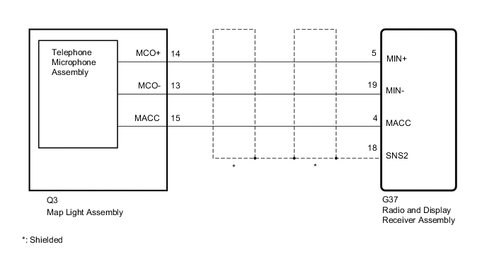
The radio and display receiver assembly and map light assembly (telephone microphone assembly) are connected to each other using the microphone connection detection signal lines.
This DTC is stored when a microphone connection detection signal line is disconnected.
| DTC No. | Detection Item | DTC Detection Condition | Trouble Area |
|---|---|---|---|
| B1579 | Voice Recognition Microphone Disconnected | Telephone microphone signal is lost |
|
WIRING DIAGRAM
CAUTION / NOTICE / HINT
Tech Tips
When replacing the radio and display receiver assembly, it is necessary to perform the vehicle contract setting for Connected Services (w/ Connected Services Function).
PROCEDURE
-
CHECK HARNESS AND CONNECTOR (RADIO AND DISPLAY RECEIVER ASSEMBLY - MAP LIGHT ASSEMBLY)
-
Disconnect the G37 radio and display receiver assembly connector.
-
Disconnect the Q3 map light assembly (telephone microphone assembly) connector.
-
Measure the resistance according to the value(s) in the table below.
Standard Resistance Tester Connection Condition Specified Condition G37-4 (MACC) - Q3-15 (MACC) Always Below 1 Ω G37-5 (MIN+) - Q3-14 (MCO+) Always Below 1 Ω G37-19 (MIN-) - Q3-13 (MCO-) Always Below 1 Ω G37-18 (SGND) - Body ground Always 10 kΩ or higher G37-4 (MACC) or Q3-15 (MACC) - Body ground Always 10 kΩ or higher G37-5 (MIN+) or Q3-14 (MCO+) - Body ground Always 10 kΩ or higher G37-19 (MIN-) or Q3-13 (MCO-) - Body ground Always 10 kΩ or higher Result Proceed to OK NG
NG 
REPAIR OR REPLACE HARNESS OR CONNECTOR
OK 
-
-
INSPECT MAP LIGHT ASSEMBLY
-
Remove the map light assembly.
-
Inspect the map light assembly.
Result Proceed to OK NG
NG
REPLACE MAP LIGHT ASSEMBLY Click here
OK
-
-
CHECK RADIO AND DISPLAY RECEIVER ASSEMBLY
-
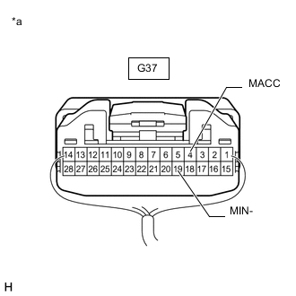
*a Component with harness connected
(Radio and Display Receiver Assembly)
Remove the radio and display receiver assembly with the connector still connected.
-
Measure the resistance according to the value(s) in the table below.
Standard Resistance Tester Connection Condition Specified Condition G37-19 (MIN-) - Body ground Always Below 1 Ω -
Measure the voltage according to the value(s) in the table below.
Standard Voltage Tester Connection Switch Condition Specified Condition G37-4 (MACC) - Body ground Ignition switch ACC 4 to 6 V Result Proceed to OK NG
NG
REPLACE RADIO AND DISPLAY RECEIVER ASSEMBLY Click here
OK
-
-
CHECK MAP LIGHT ASSEMBLY
-
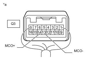
*a Component with harness connected
(Map Light Assembly)
Reconnect the map light assembly with the connector still connected.
-
Turn the ignition switch to ACC.
-
Connect an oscilloscope to terminals Q3-14 (MCO+) and Q3-13 (MCO-) of the map light assembly connector.
-
Check the waveform of the telephone microphone assembly using the oscilloscope.
Result Result Proceed to A waveform synchronized with the voice input to the map light assembly is not output. A A waveform synchronized with the voice input to the map light assembly is output. B
A
REPLACE TELEPHONE MICROPHONE ASSEMBLY Click here
B
REPLACE RADIO AND DISPLAY RECEIVER ASSEMBLY Click here
-